ARM7TDMI 查看數據表(PDF) - Unspecified
零件编号
产品描述 (功能)
生产厂家
ARM7TDMI Datasheet PDF : 284 Pages
| |||
Preface
Timing diagram conventions
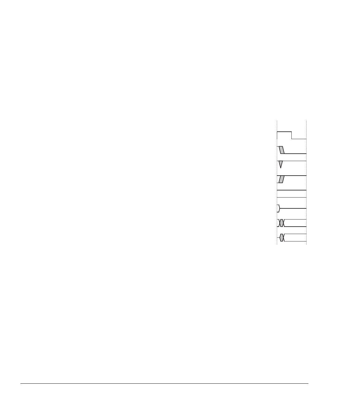
The key provided in Figure P-1 explains the components used in timing diagrams. Any
variations are labeled when they occur. Therefore, no additional meaning must be
attached unless specifically stated.
Shaded bus and signal areas are undefined, so the bus or signal can assume any value
within the shaded area at that time. The actual level is unimportant and does not affect
normal operation.
Clock
HIGH to LOW
Transient
HIGH/LOW to HIGH
Bus stable
Bus to high impedance
Bus change
High impedance to stable bus
Figure P-1 Key to timing diagram conventions
xx
Copyright © 1994-2001. All rights reserved.
ARM DDI 0029G
Share Link: 