MAC212A8FP 查看數據表(PDF) - Motorola => Freescale
零件编号
产品描述 (功能)
生产厂家
MAC212A8FP Datasheet PDF : 6 Pages
| |||
MOTOROLA
SEMICONDUCTOR TECHNICAL DATA
Order this document
by MAC212FP/D
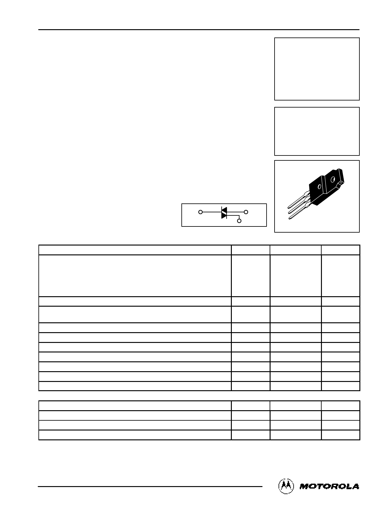
Triacs
Silicon Bidirectional Thyristors
MAC212FP
Series
MAC212AFP
Series
. . . designed primarily for full-wave ac control applications, such as light dimmers,
motor controls, heating controls and power supplies; or wherever full-wave silicon
gate controlled solid-state devices are needed. Triac type thyristors switch from a
blocking to a conducting state for either polarity of applied anode voltage with positive
or negative gate triggering.
• Blocking Voltage to 800 Volts
• All Diffused and Glass Passivated Junctions for Greater Parameter Uniformity
and Stability
• Small, Rugged, Thermowatt Construction for Low Thermal Resistance, High Heat
Dissipation and Durability
• Gate Triggering Guaranteed in Three Modes (MAC212FP Series) or
Four Modes (MAC212AFP Series)
MT2
MT1
G
ISOLATED TRIACs
THYRISTORS
12 AMPERES RMS
200 thru 800 VOLTS
CASE 221C-02
STYLE 3
MAXIMUM RATINGS (TJ = 25°C unless otherwise noted.)
Rating
Symbol
Value
Unit
Repetitive Peak Off-State Voltage(1) (TJ = –40 to +125°C,
1/2 Sine Wave 50 to 60 Hz, Gate Open)
VDRM
MAC212-4FP, MAC212A4FP
200
MAC212-6FP, MAC212A6FP
400
MAC212-8FP, MAC212A8FP
600
MAC212-10FP, MAC212A10FP
800
Volts
On-State RMS Current (TC = +85°C) Full Cycle Sine Wave 50 to 60 Hz(2)
IT(RMS)
12
Amps
Peak Nonrepetitive Surge Current (One Full Cycle, 60 Hz, TC = +85°C)
preceded and followed by rated current
ITSM
100
Amps
Circuit Fusing (t = 8.3 ms)
I2t
40
A2s
Peak Gate Power (TC = +85°C, Pulse Width = 10 µs)
Average Gate Power (TC = +85°C, t = 8.3 ms)
PGM
20
PG(AV)
0.35
Watts
Watt
Peak Gate Current (TC = +85°C, Pulse Width = 10 µs)
p RMS Isolation Voltage (TA = 25°C, Relative Humidity 20%)
IGM
V(ISO)
2
1500
Amps
Volts
Operating Junction Temperature
TJ
–40 to +125
°C
Storage Temperature Range
Tstg
–40 to +150
°C
THERMAL CHARACTERISTICS
Characteristic
Symbol
Max
Unit
Thermal Resistance, Junction to Case
RθJC
2.1
°C/W
Thermal Resistance, Case to Sink
RθCS
2.2 (typ)
°C/W
Thermal Resistance, Junction to Ambient
RθJA
60
°C/W
1. VDRM for all types can be applied on a continuous basis. Blocking voltages shall not be tested with a constant current source such that the
voltage ratings of the devices are exceeded.
2. The case temperature reference point for all TC measurements is a point on the center lead of the package as close as possible to the plastic
body.
Motorola Thyristor Device Data
1
© Motorola, Inc. 1995
Share Link: 