RT9921PQV 查看數據表(PDF) - Richtek Technology
零件编号
产品描述 (功能)
生产厂家
RT9921PQV Datasheet PDF : 15 Pages
| |||
Preliminary
RT9921
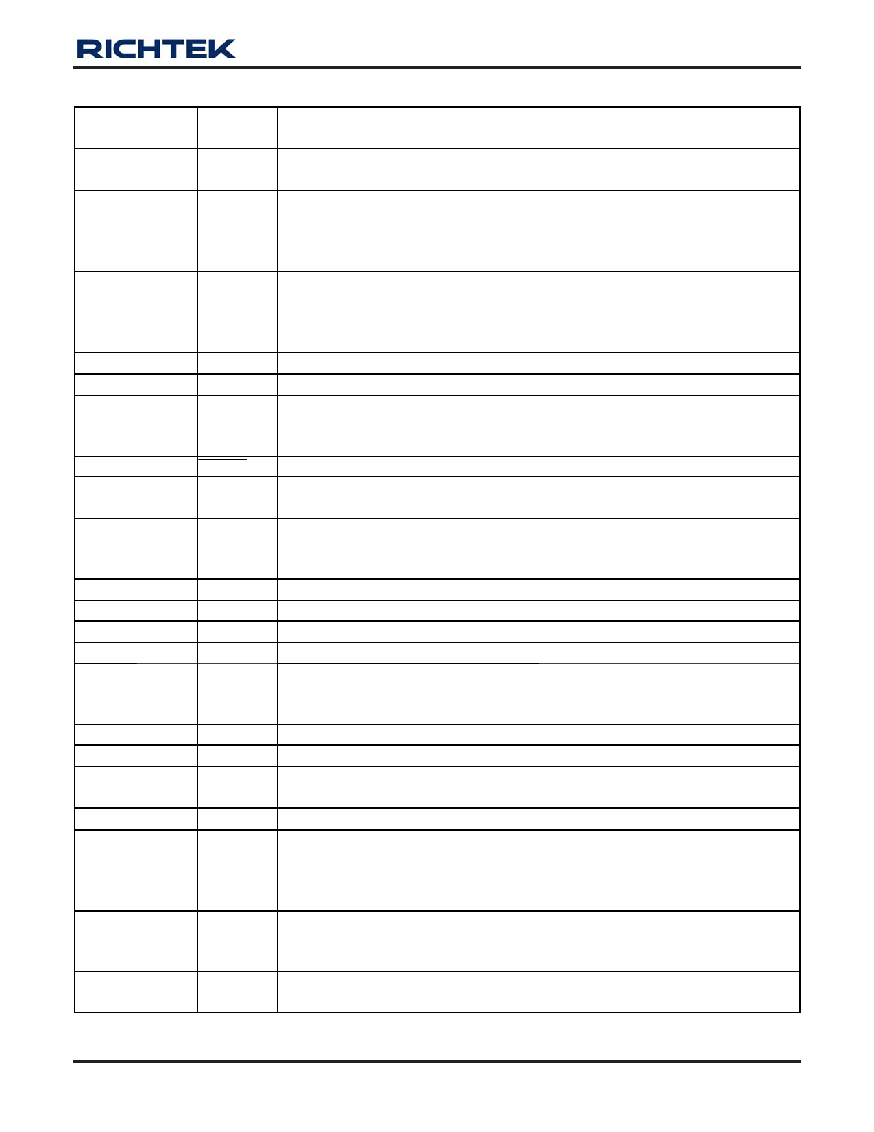
Functional Pin Description
Pin No.
Pin Nam e Pin Function
1
LX
Switching Pin. Drain of the internal power NMOS for the main step-up regulator.
Supply Input. The supply voltage powers all the control circuits including the boost
2
VIN
converter, negative linear-regulator and gate pulse regulator and voltage detector.
3
SS
4,
AGND
Exposed Pad (25)
Soft-Start Control Pin. Connect a soft-start capacitor (CSS) to this pin. The
soft-start capacitor is charged with a constant current 4μA.
Analog Ground. The exposed pad must be soldered to a large PCB and connected
to GND for maximum power dissipation.
Low-Dropout Linear Regulator (LDO) Feedback Input. ADJ regulates to 1.24V
5
ADJ
nominal. Connect ADJ to the center of a resistive voltage-divider between the LDO
output voltage LDOO and the analog ground (AGND) the LDO output voltage.
Place the resistive voltage-divider close to the pin.
6
L DOO
Voltage Output of the LDO.
7
L DOI
Voltage Input for the LDO.
Voltage Detector Divider Input. Connect VDIV to the center of a resistive
8
VDIV
voltage-divider between the detected voltage input (VDI) and analog ground
(AGND).
9
RESET Voltage Detector Output for Reset. Active Low.
10
CD
Pin for external capacitor setting the delay time for voltage detector reset delay
time. The delay time tD = 120k x CD sec, where CD is the capacitance value.
High-Voltage Switch Delay Input. Connect a capacitor from VDPM to GND to set
11
VDPM
the delay time. A 20μA current source charges CDPM.
Power on delay time = 62k x CDPM.
12
VFLK
VFLK is p roduced by tim ing con tro ller http://www.DataSheet4U.net/ for cha rg ing or disch argin g VGH M.
13
RE
Switch Input for Discharge VGHM.
14
VGHM
VGHM is the Supply Voltage for the Gate Driver ICs.
15
VGH
Switch Input for Charge VGHM.
Voltage Feedback to Determine Gate-High Regulator’s Output Voltage. Connect
16
FBP
FBP to the center of a resistive voltage-divider between the output voltage VGH
and GND. Place the resistive voltage-divider close to the pin.
17
D RVP
Voltage Driver Output of Gate-High Regulator.
18
AVDD
VDD for Source Driver Power. This also supplies the GPM/OPA block.
19
OPAO
Unity-Gain OPA output pin.
20
OPAI
Unity-Gain OPA input Pin.
21
C OM P
Compensation Pin for Error Amplifier. Connect a compensation network to ground.
Main Boost Regulator Feedback Input. FB regulates to 1.24V nominal. Connect
22
FB
FB to the center of a resistive voltage-divider between the main output AVDD and
the analog ground (AGND) the boost regulator output voltage. Place the resistive
voltage-divider close to the pin.
Boost Converter Frequency Select Input. When FREQ is low, the oscillator
23
FREQ
frequency is set to 640kHz. When FREQ is high, the frequency is 1.2MHz. This
input has a 5uA pull-down current.
Power Ground. PGND is the source of the power NMOS. Connect PGND to the
24
PGND
analog ground (AGND) at the device’s pins.
DS9921-00 November 2007
www.richtek.com
3
datasheet pdf - http://www.DataSheet4U.net/
Share Link: 