DT28F800F3B95 查看數據表(PDF) - Intel
零件编号
产品描述 (功能)
生产厂家
DT28F800F3B95 Datasheet PDF : 47 Pages
| |||
E
FAST BOOT BLOCK DATASHEET
CLK (C)
A19-0 (A)
ADV# (V)
DQ15-0 (D/Q)
DQ15-0 (D/Q)
DQ15-0 (D/Q)
DQ15-0 (D/Q)
DQ15-0 (D/Q)
Valid
Address
Code 2
Code 3
Code 4
Code 5
Code 6
Valid
Output
Valid
Output
Valid
Output
Valid
Output
Valid
Output
Valid
Output
Valid
Output
Valid
Output
Valid
Output
Valid
Output
Valid
Output
Valid
Output
Valid
Output
Valid
Output
Valid
Output
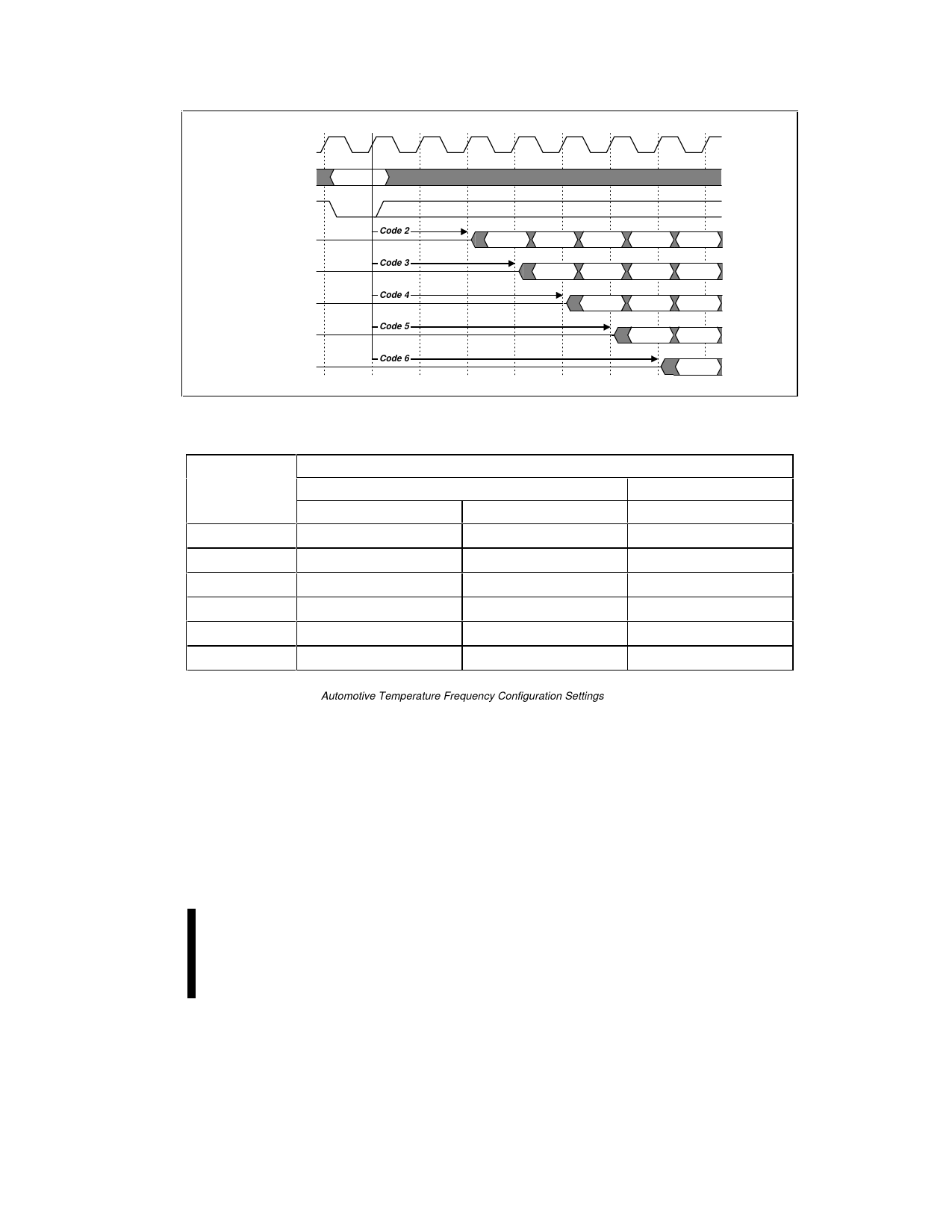
Figure 5. Frequency Configuration
Table 7. Frequency Configuration Settings(1)
Frequency
Input CLK Frequency
Configuration
Product = -90
Product = -120
Code
VCC = 3.0 V-3.6 V
VCC = 2.7 V-3.6 V
VCC = 2.7 V-3.6 V
1
Reserved
Reserved
Reserved
2
≤ 27 MHz
≤ 25 MHz
≤ 20 MHz
3
≤ 40 MHz
≤ 33 MHz
≤ 28 MHz
4
≤ 54 MHz
≤ 50 MHz
≤ 40 MHz
5
≤ 66 MHz
≤ 60 MHz
≤ 50 MHz
6
-
≤ 66 MHz
≤ 60 MHz
NOTES:
1. Reference Section 4.1. Automotive Temperature Frequency Configuration Settings for the corresponding frequency
configuration codes to different input CLK frequencies.
4.9 Set Read Configuration
Command
The Set Read Configuration command writes data
to the read configuration register. This operation is
initiated by a two-cycle command sequence. Read
configuration setup is written, followed by a second
write that specifies the data to be written to the read
configuration register. This data is placed on the
address bus, A15:0, and is latched on the rising
edge of ADV#, CE#, or WE# (whichever occurs
PRODUCT PREVIEW
first). The read configuration data sets the device’s
read configuration, burst order, frequency
configuration, and burst length. The command
functions independently of the applied VPP voltage.
After executing this command, the device returns to
read array mode.
4.9.1
READ CONFIGURATION
The device supports two high performance read
configurations: asynchronous page-mode and
19
Share Link: 