MAX6975 查看數據表(PDF) - Maxim Integrated
零件编号
产品描述 (功能)
生产厂家
MAX6975 Datasheet PDF : 23 Pages
| |||
24-Output PWM LED Drivers
for Message Boards
The serial interface uses the continuously running
clock, CLKI, to synchronously transfer and latch data
(33MHz max). The MAX6974/MAX6975 sample inputs
DIN and LOADI on the rising edge of CLKI and update
outputs DOUT and LOADO on the rising edge of CLKI.
The MAX6974/MAX6975 specifications guarantee that
cascaded devices observe setup and hold timing from
device to device, making external buffers and clock
trees unnecessary, even in very large systems.
The high-speed CLKI, CLKO, DIN, and DOUT signals
use low-voltage differential signaling (LVDS), and the
less frequently changing control signals, LOADI and
LOADO, use standard CMOS. The differential signals
are generally referred to in unipolar shorthand; for
example, the statement “CLKI rising edge” means that
CLKI+ is rising, and CLKI- is falling.
The MAX6974/MAX6975 use LVDS drivers with differential
signaling (300mV nominal logic swing around a +1.2V
bias) and cascaded CMOS control signals to minimize
signal-path EMI and simplify interface timing and print-
ed-circuit board (PCB) layout. Note the differential
inputs for the first driver can be driven from +3.3V
CMOS using LVDS level translators, such as the
MAX9112 terminated with 110Ω (see Figure 12).
A 25MHz to 33MHz clock frequency is recommended
to keep the display refresh rate high. When using the
MAX6975 in reduced global-intensity mode (GLB4 = 1
in configuration register), the recommended clock
frequency range is 6MHz to 33MHz.
Serial-Interface Protocol Structure
The MAX6974/MAX6975 serial interface transfers all
data and control functions using a protocol structure
consisting of header, data, and optional tail segments
transmitted in this sequence. The header and tail
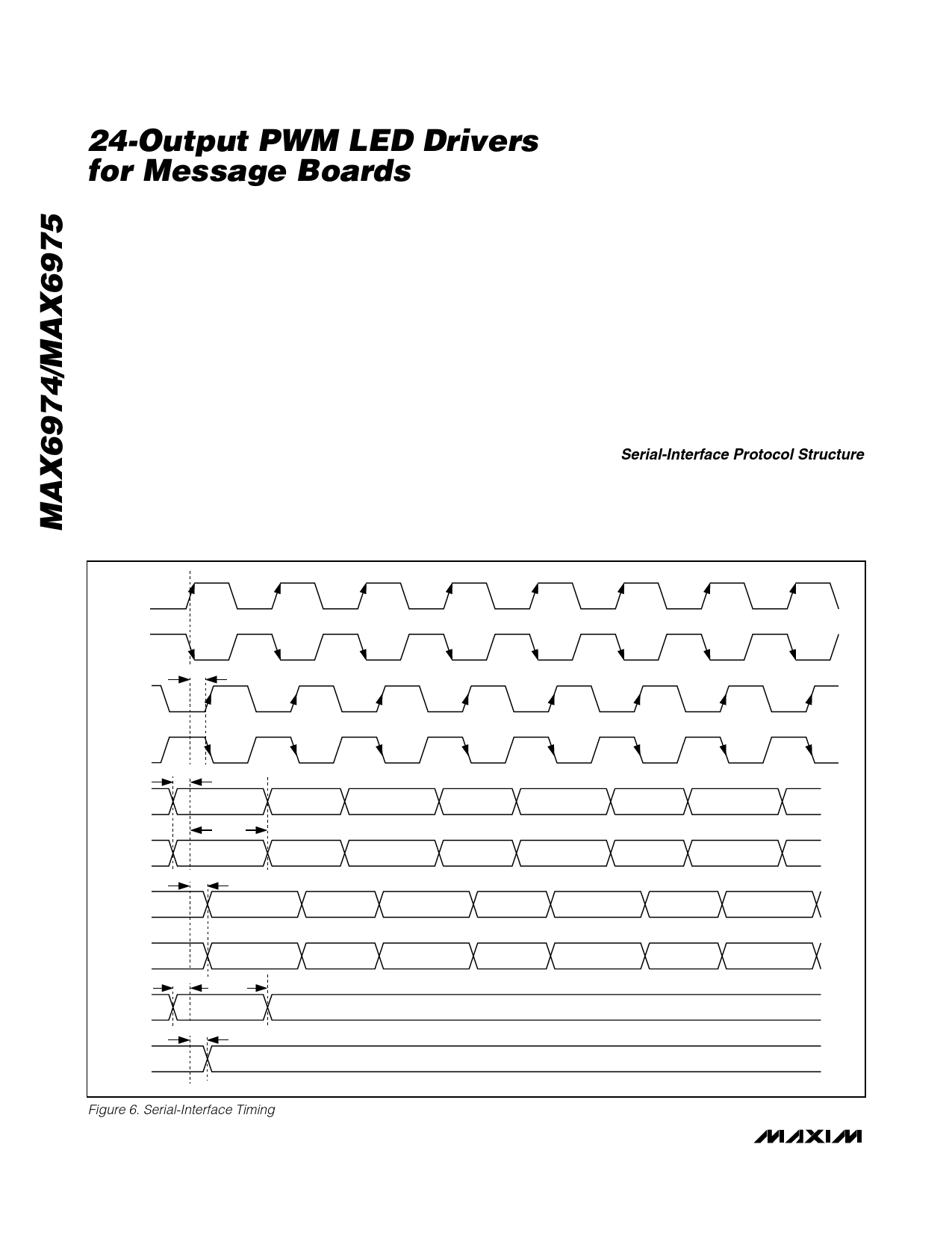
CLKI+
CLKI-
CLKO+
tPD-CLKO
CLKO-
tSU-DIN
DIN+
DIN-
DOUT+
tHD-DIN
tPD-DOUT
DOUT-
LOADI
tSU-LOADI
tHD-LOADI
tPD-LOADO
LOADO
Figure 6. Serial-Interface Timing
16 ______________________________________________________________________________________
Share Link: 