BTS7741G 查看數據表(PDF) - Infineon Technologies
零件编号
产品描述 (功能)
生产厂家
BTS7741G Datasheet PDF : 16 Pages
| |||
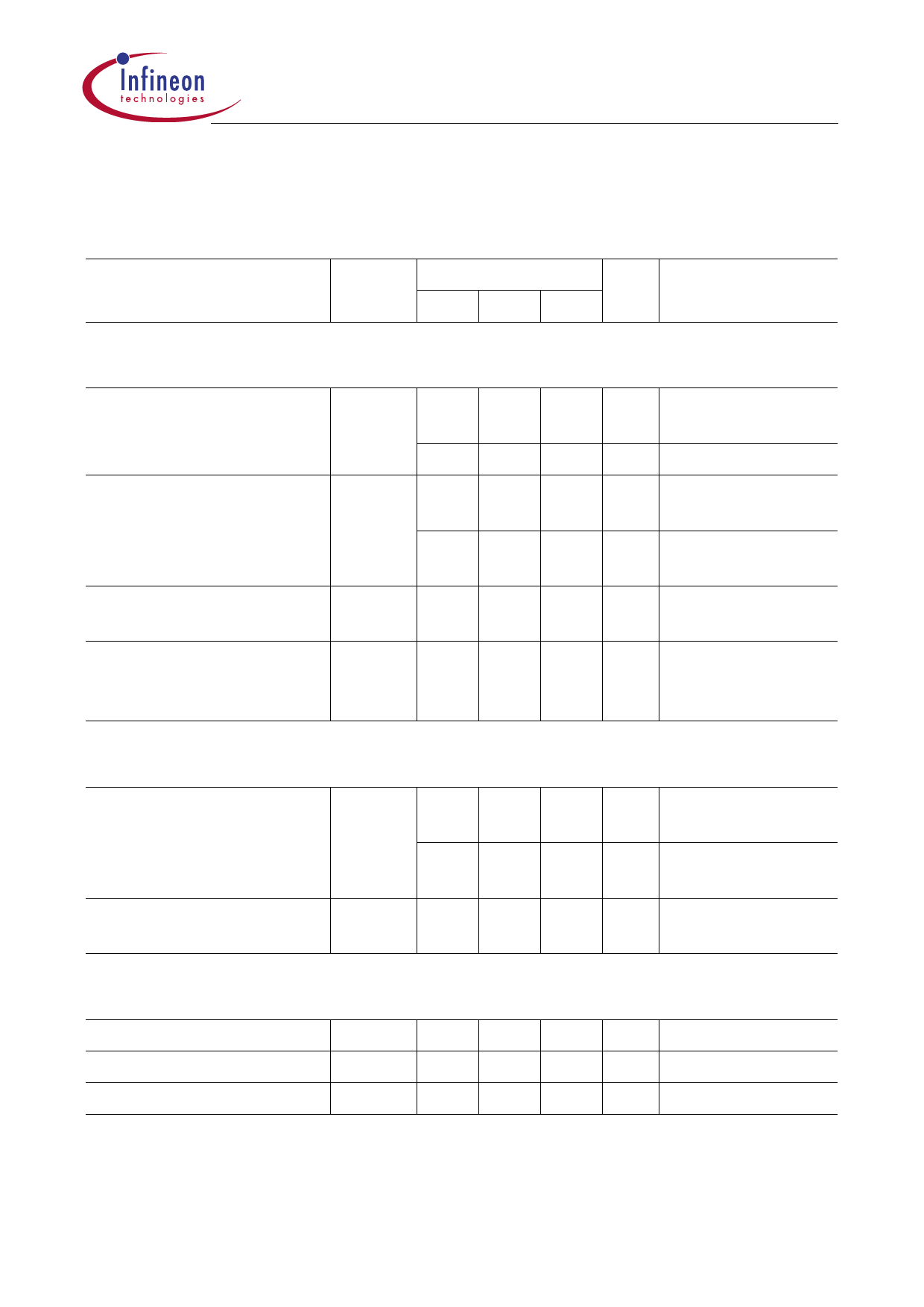
BTS 7741 G
3.3 Electrical Characteristics
ISH1 = ISH2 = ISL1 = ISL2 = 0 A; – 40 °C < Tj < 150 °C; 8 V < VS < 18 V
unless otherwise specified
Parameter
Symbol Limit Values Unit Test Condition
min. typ. max.
Current Consumption HS-switch
Quiescent current
IS
–
Supply current
–
IS
–
–
Leakage current of
high-side switch
ISH LK
–
Leakage current through ILKCL = –
logic GND in free wheeling IFH + ISH
condition
5
8
–
12
1.5 3
3
6
–
6
–
10
µA IH1 = IH2 = 0 V
Tj = 25 °C
µA IH1 = IH2 = 0 V
mA IH1 or IH2 = 5 V
VS = 12 V
mA IH1 and IH2 = 5 V
VS = 12 V
µA VIH = VSH = 0 V
mA IFH = 3 A
Current Consumption LS-switch
Input current
IIL
–
–
Leakage current of low-side IDL LK
–
switch
8
30 µA VIL = 5 V;
normal operation
160 300 µA VIL = 5 V;
failure mode
2
10 µA VIL = 0 V
Under Voltage Lockout (UVLO) HS-switch
Switch-ON voltage
VUVON
–
–
Switch-OFF voltage
VUVOFF 1.8 –
Switch ON/OFF hysteresis VUVHY –
1
4.8 V
3.5 V
–
V
VS increasing
VS decreasing
V V – UVON
UVOFF
Data Sheet
9
2003-03-06
Share Link: 