LXT970AQC 查看數據表(PDF) - Intel
零件编号
产品描述 (功能)
生产厂家
LXT970AQC Datasheet PDF : 74 Pages
| |||
Dual-Speed Fast Ethernet Transceiver — LXT970A
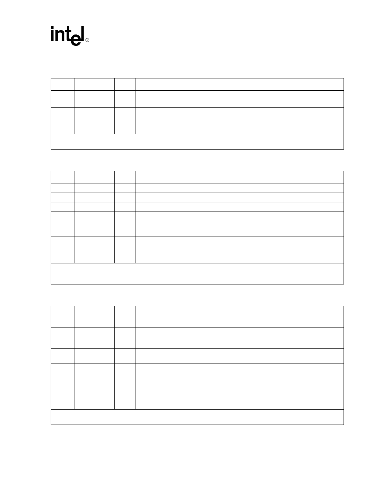
Table 4. LXT970A Twisted-Pair Interface Signal Descriptions
Pin#1
Pin Name
I/O2
Signal Description
21
23
TPOP
TPON
AO
Twisted-Pair Output, Positive and Negative. Differential driver pair produces 802.3-
compliant pulses for either 100BASE-TX or 10BASE-T transmission.
20
TREF
AO Transmit Reference. Tie to center tap of output transformer.
29
30
TPIP
TPIN
AI
Twisted-Pair Input, Positive and Negative. Differential input pair for either 100BASE-TX
or 10BASE-T reception.
1. Pin numbers apply to all package types.
2. I/O Column Coding: I = Input, O = Output, OD = Open Drain, A = Analog
Table 5. LXT970A LED Indicator Signal Descriptions
Pin#1
Pin Name
I/O2
Signal Description3
38
LEDS
O Speed LED. Active Low output indicates 100 Mbps operation is selected.
42
LEDR
O Receive LED. Active Low output indicates that receiver is active.
41
LEDT
O Transmit LED. Active Low output indicates transmitter is active.
Link LED. Active Low output;
40
LEDL
O During 100 Mbps operation, indicates scrambler lock and receipt of valid Idle codes.
During 10 Mbps operation, indicates Link Valid status.
Collision LED. In default mode, active Low output indicates collision. However, LEDC is
39
LEDC
O
programmable and may be set for other indications. For programming options, see
Configuration Register 19 in Table 55, “Configuration Register (Address 19, Hex 13)” on
page 71.
1. Pin numbers apply to all package types.
2. I/O Column Coding: I = Input, O = Output, OD = Open Drain, A = Analog.
3. LEDs are read at power-up to determine scrambler seed values.
Table 6. LXT970A Miscellaneous Signal Descriptions
Pin#1
Pin Name
I/O2
Signal Description
10
TEST
I Test. Must be tied Low.
12
XI
I
Crystal Input and Output. Use a clock at XI or connect a 25 MHz crystal oscillator across
XI and XO. Refer to the Functional Description section for detailed clock requirements on
11
XO
O page 18.
25
RBIAS
AI
Bias Control. Controls operating circuit bias via an external 22.1 kΩ, 1% resistor to
ground.
16
RESET
I
Reset. This active Low input is OR’ed with the control register Reset bit (0.15). The
LXT970A reset cycle is extended 300 µs (nominal) after Reset is de-asserted.
34
PWRDWN
I
Power Down. When High, forces LXT970A into power down mode. This pin is OR’ed with
the Power Down bit (0.11). Refer to Table 45 for more information.
32, 35,
36
N/C
- No Connection. Leave open.
1. Pin numbers apply to all package types.
2. I/O Column Coding: I = Input, O = Output, OD = Open Drain, A = Analog.
Datasheet
13
Share Link: 