24IMS6-1515-9 查看數據表(PDF) - Power-One Inc.
零件编号
产品描述 (功能)
生产厂家
24IMS6-1515-9 Datasheet PDF : 13 Pages
| |||
Industrial Environment
DC/DC Converters < 40W
IMS6 Series
Cleaning Agents
In order to avoid possible damage, any penetration of
cleaning fluids has to be prevented, since the power sup-
plies are not hermetically sealed.
Protection Degree
The protection degree of the DC-DC converters is IP 30.
Isolation
The electric strength test is performed as factory test in ac-
cordance with IEC/EN 60950 and UL 1950 and should not
be repeated in the field. Melcher will not honour any guar-
antee claims resulting from electric strength field tests.
Table 14: Electric strength test voltages
Characteristic
Input - Output
24/48 IMS 6
Electric strength
1.2
test voltage 1 s
1.5
Coupling
1.2
capacitance
Insulation resist.
at 500 V DC
>100
Partial discharge
extinction voltage
Consult factory
Unit
kVrms
kV DC
nF
M
kV
Table 15: Insulation concept leading to an SELV output circuit
Conditions Front end
Supply
voltage
Minimum required grade Maximum
of isolation, to be provided DC output
by the AC-DC front end, voltage
including mains supplied from the
battery charger
front end 1
Minimum required safety
status of the front end
output circuit
Mains
Basic
250 V AC
60 V
Earthed SELV circuit 2
ELV circuit
>60 V
Hazardous voltage
secondary circuit
Double or reinforced
60 V
SELV circuit
DC-DC converter
Measures to achieve the
specified safety status of the
output circuit
Result
Safety status of
the DC-DC
converter output
circuit
Operational insulation, pro-
vided by the DC-DC converter
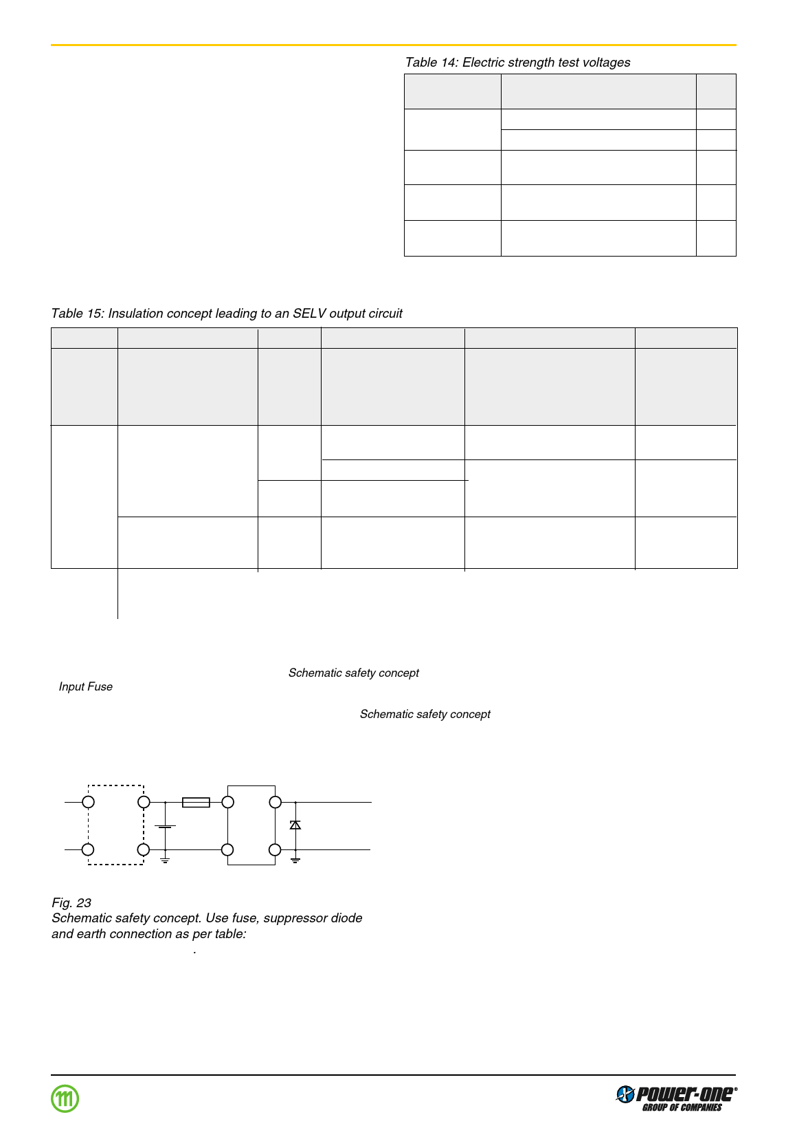
Input fuse 3 output suppressor
diodes 4, and earthed
output circuit 2
SELV circuit
Earthed SELV
circuit
Operational insulation, pro- SELV circuit
vided by the DC-DC converter
1 The front end output voltage should match the specified input voltage range of the DC-DC converter.
2 The earth connection has to be provided by the installer according to the relevant safety standard, e.g. IEC/EN 60950.
3 The installer shall provide an approved fuse (type with the lowest rating suitable for the application) in a non-earthed input line directly
at the input of the DC-DC converter (see fig.: Schematic safety concept). For UL’s purpose, the fuse needs to be UL-listed. See also:
Input Fuse.
4 Each suppressor diode should be dimensioned in such a way, that in the case of an insulation fault the diode is able to limit the output
voltage to SELV (<60 V) until the input fuse blows (see fig.: Schematic safety concept).
5 Has to be insulated from earth by double or reinforced insulation according to the relevant safety standard, based on the maximum
output voltage from the front end.
~
Mains
~
AC-DC
front
end
Fuse
DC-DC
Battery con-
verter
10004
+
Suppressor
diode SELV
–
Earth
connection
Earth
connection
Fig. 23
Schematic safety concept. Use fuse, suppressor diode
and earth connection as per table: Safety concept leading
to an SELV output circuit.
Edition 1 06.00
Share Link: 