AM28F010A-70FI 查看數據表(PDF) - Advanced Micro Devices
零件编号
产品描述 (功能)
生产厂家
AM28F010A-70FI
Advanced Micro Devices

AM28F010A-70FI Datasheet PDF : 35 Pages
| |||
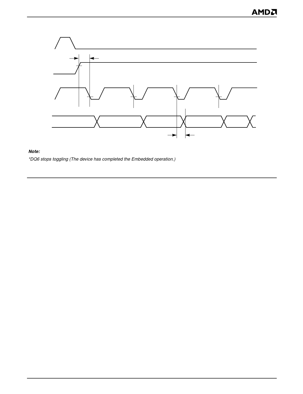
CE#
WE#
tOEH
OE#
Data
DQ0–DQ7
DQ6 =
DQ6 =
*
DQ6
DQ0–DQ7
Stop Toggling
Valid
tOE
Note:
*DQ6 stops toggling (The device has completed the Embedded operation.)
Figure 6. AC Waveforms for Toggle Bit during Embedded Algorithm Operations
16778D-11
DQ5
Exceeded Timing Limits
DQ5 will indicate if the program or erase time has
exceeded the specified limits. This is a failure condi-
tion and the device may not be used again (internal
pulse count exceeded). Under these conditions DQ5
will produce a “1.” The program or erase cycle was not
successfully completed. Data# Polling is the only op-
erating function of the device under this condition. The
CE# circuit will partially power down the device under
these conditions (to approximately 2 mA). The OE#
and WE# pins will control the output disable functions
as described in the Command Definitions table in the
corresponding device data sheet.
Parallel Device Erasure
The Embedded Erase algorithm greatly simplifies par-
allel device erasure. Since the erase process is internal
to the device, a single erase command can be given to
multiple devices concurrently. By implementing a paral-
lel erase algorithm, total erase time may be minimized.
Note that the Flash memories may erase at different
rates. If this is the case, when a device is completely
erased, use a masking code to prevent further erasure
(over-erasure). The other devices will continue to erase
until verified. The masking code applied could be the
read command (00h).
Power-Up/Power-Down Sequence
The device powers-up in the Read only mode. Power
supply sequencing is not required. Note that if VCC ≤
1.0 Volt, the voltage difference between VPP and VCC
should not exceed 10.0 Volts. Also, the device has a
rise VPP rise time and fall time specification of 500 ns
minimum.
Reset Command
The Reset command initializes the Flash memory de-
vice to the Read mode. In addition, it also provides the
user with a safe method to abort any device operation
(including program or erase).
The Reset must be written two consecutive times after
the Setup Program command (10h or 50h). This will
reset the device to the Read mode.
Following any other Flash command, write the Reset
command once to the device. This will safely abort any
previous operation and initialize the device to the Read
mode.
The Setup Program command (10h or 50h) is the only
command that requires a two-sequence reset cycle. The
first Reset command is interpreted as program data.
However, FFh data is considered as null data during pro-
gramming operations (memory cells are only pro-
grammed from a logical “1" to “0"). The second Reset
command safely aborts the programming operation and
resets the device to the Read mode.
Memory contents are not altered in any case.
Am28F010A
17
Share Link: