AAT3682 查看數據表(PDF) - Advanced Analogic Technologies
零件编号
产品描述 (功能)
生产厂家
AAT3682 Datasheet PDF : 18 Pages
| |||
AAT3682
Lithium-Ion/Polymer Linear Battery Charger
VIN
R2
2
1
C1
0.2Ω
J1
GND
22μF R1
2.2K
R5
100K
C5
4.7μF
U1
AAT3682
R3
1K
C4
1000pF
1 TS
N/C 12
D2
Green LED
2 N/C
3 N/C
4 STAT
GATE 11
VSS 10
BAT 9
J2
1
Remove capacitor for
progressive dimming
C3
47nF
R6
100K
D1
C2
10μF
2
3
R4
1K
R7
100K
3 S1
2
1
SW-T2X
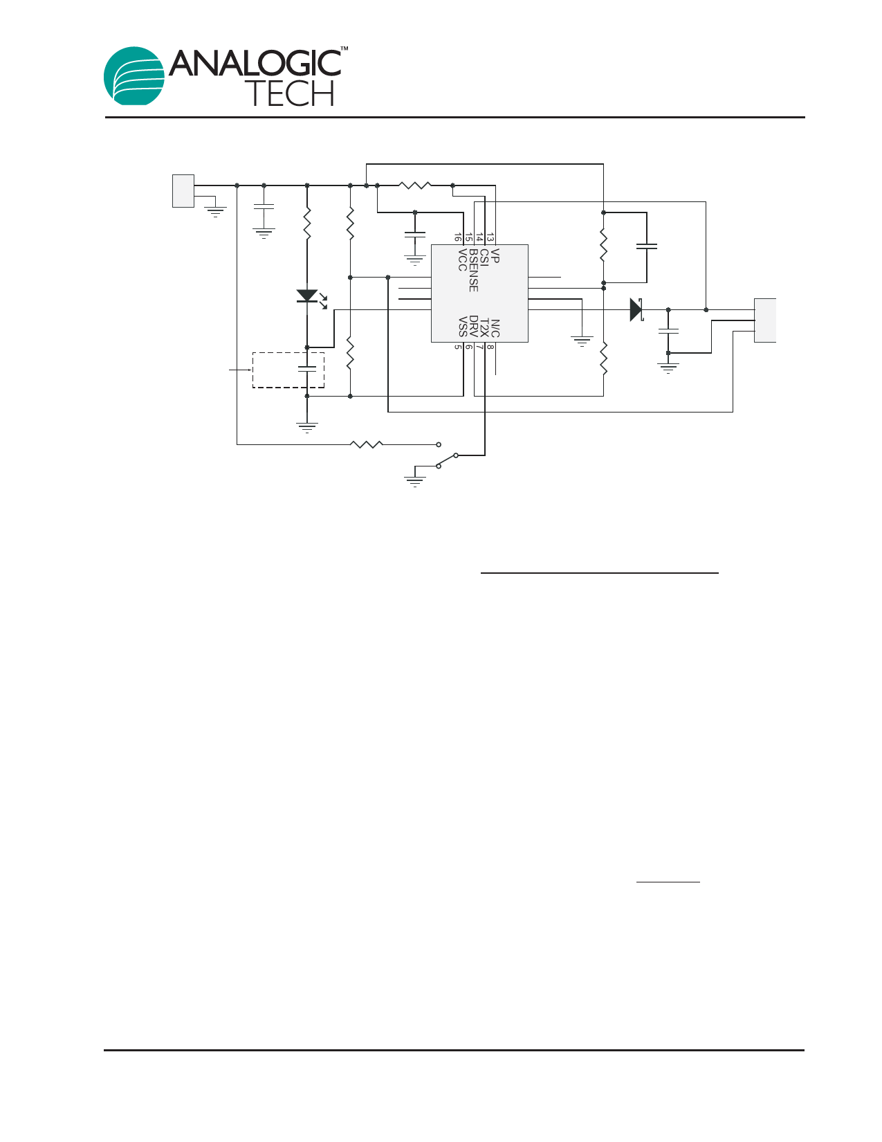
Figure 5: Evaluation Board Schematic.
Protection Circuitry
The AAT3682 is a highly integrated battery manage-
ment system IC including several protection fea-
tures. In addition to battery temperature monitoring,
the IC constantly monitors for over-current and over-
voltage conditions; if an over-current situation
occurs, the AAT3682 latches off the pass device to
prevent damage to the battery or the system, and
enters shutdown mode until the over-current event is
terminated. An over-voltage condition is defined as a
condition where the voltage on the BAT pin exceeds
the maximum battery charge voltage. If an over-volt-
age condition occurs, the IC turns off the pass
device until voltage on the BAT pin drops below the
maximum battery charge constant voltage threshold.
The AAT3682 will resume normal operation after the
over-current or over-voltage condition is removed.
During an over-current or over-voltage event, the
STAT will report a FAULT signal. In the event of a
battery over-temperature condition, the IC will turn
off the pass device and report a FAULT signal on the
STAT pin. After the system recovers from a temper-
ature fault, the IC will resume operation in the 1X
trickle charge mode to prevent damage to the sys-
tem in the event a defective battery is placed under
charge. Once the battery voltage rises above the
trickle charge to constant current charge threshold,
the IC will resume the constant current mode.
3682.2006.12.1.3
Applications Information
Choosing a Sense Resistor
The charging rate recommended by lithium-
ion/polymer cell vendors is normally 1C, with a 2C
absolute maximum rating. Charging at the highest
recommended rate offers the advantage of short-
ened charging time without decreasing the battery's
lifespan. This means that the suggested fast
charge rate for a 500mAH battery pack is 500mA.
Refer to the Safe Operating Area curves in the
Typical Characteristics section of this datasheet to
determine the maximum allowable charge current
for a given input voltage. The current sense resistor,
RSENSE, programs the charge current according to
the following equation:
RSENSE =
VCC - VCSI
ICHARGE
Where ICHARGE is the desired typical charge current
during constant current charge mode. VCC - VCSI is
the voltage across RSENSE, shown in the Electrical
Characteristics table as VCS. To program a nominal
500mA charge current during fast charge, a
200mΩ value resistor should be selected.
13
Share Link: 