MAX1700EEE 查看數據表(PDF) - Maxim Integrated
零件编号
产品描述 (功能)
生产厂家
MAX1700EEE Datasheet PDF : 16 Pages
| |||
1-Cell to 3-Cell, High-Power (1A),
Low-Noise, Step-Up DC-DC Converters
ELECTRICAL CHARACTERISTICS (continued)
(CLK/SEL = ONA = ONB = FB = PGND = GND, OUT = POUT, VOUT = 3.6V, MAX1701: AIN = LBN = GND, LBP = REF,
TA = -40°C to +85°C, unless otherwise noted.) (Note 8)
PARAMETER
CONDITIONS
MIN TYP MAX UNITS
LOGIC AND CONTROL INPUTS
Input Low Voltage (Note 7)
Input High Voltage (Note 7)
Input High Voltage (Note 7)
Logic Input Current
1.2V < VOUT < 5.5V, ONA and ONB
2.5V < VOUT < 5.5V, CLK/SEL
1.2V < VOUT < 5.5V, ONA and ONB
2.5V < VOUT < 5.5V, CLK/SEL
ONA, ONB, and CLK/SEL
0.8VOUT
0.8VOUT
-1
0.2VOUT
V
0.2VOUT
V
1
µA
Internal Oscillator Frequency CLK/SEL = OUT
260
340 kHz
Oscillator Maximum Duty Cycle
80
92
%
External Clock Frequency
Range
200
400 kHz
Note 1: Operating voltage. Since the regulator is bootstrapped to the output, once started it will operate down to 0.7V input.
Note 2: Start-up is tested with the circuit of Figure 2.
Note 3: In low-power mode (CLK/SEL = GND), the output voltage regulates 1% higher than low-noise mode (CLK/SEL = OUT or
synchronized).
Note 4: The regulator is in start-up mode until this voltage is reached. Do not apply full load current.
Note 5: Load regulation is measured from no-load to full load where full load is determined by the N-channel switch current limit.
Note 6: Supply current from the 3.30V output is measured between the 3.30V output and the OUT pin. This current correlates
directly to the actual battery supply current, but is reduced in value according to the step-up ratio and efficiency. Set VOUT
= 3.6V to keep the internal switch open when measuring the current into the device.
Note 7: ONA and ONB have hysteresis of approximately 0.15xVOUT.
Note 8: Specifications to -40°C are guaranteed by design and not production tested.
(TA = +25°C, unless otherwise noted.)
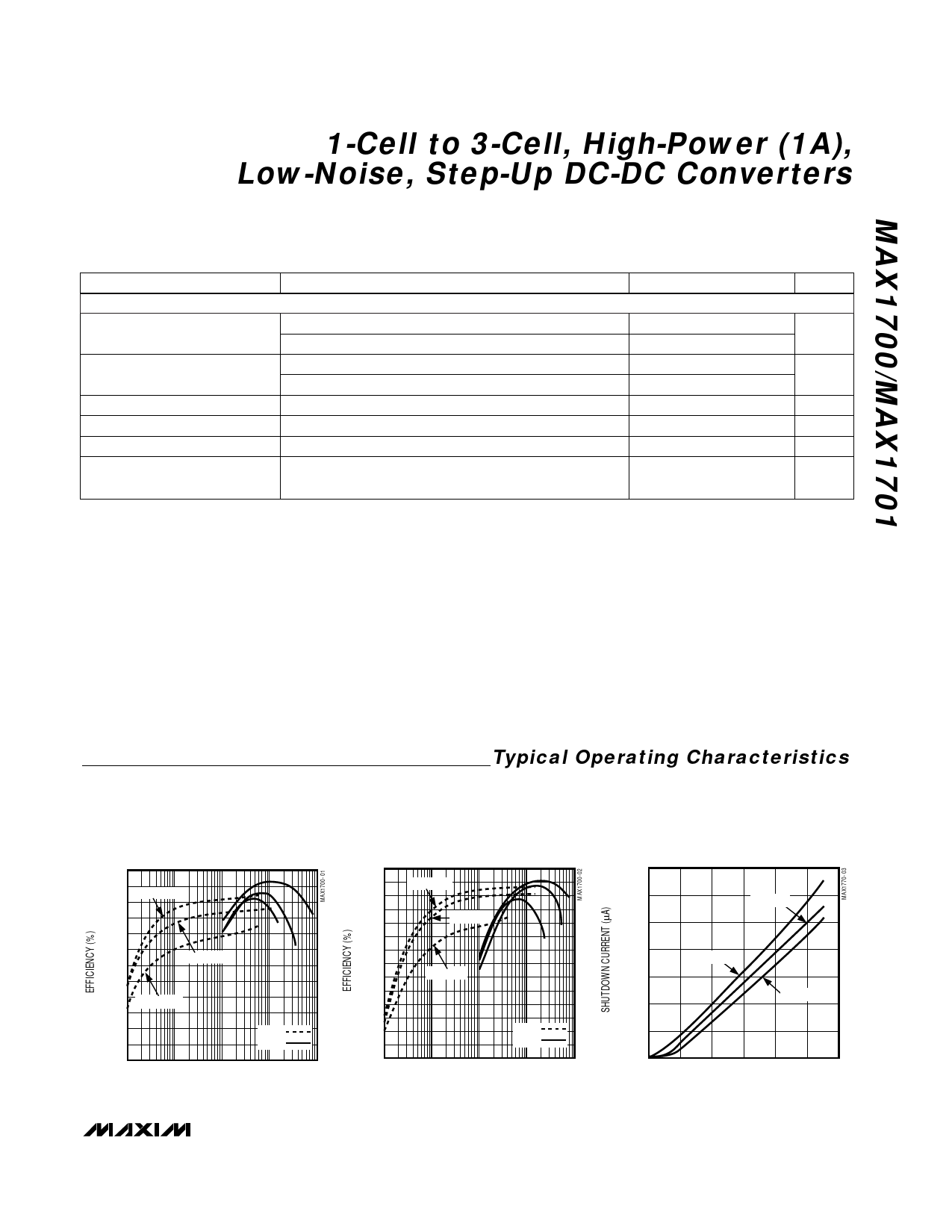
Typical Operating Characteristics
EFFICIENCY vs. LOAD CURRENT
(VOUT = 3.3V)
100
VIN = 2.4V
90
80
70
VIN = 1.2V
60 VIN = 0.9V
50
40
0.1
PFM
PWM
1
10
100
1000
LOAD CURRENT (mA)
EFFICIENCY vs. LOAD CURRENT
(VOUT = 5V)
100
VIN = 3.6V
90
80
VIN = 2.4V
70
60
VIN = 1.2V
50
40
30
0.1
PFM
PWM
1
10
100
1000
LOAD CURRENT (mA)
7.0
6.0
5.0
4.0
3.0
2.0
1.0
0
0
MAX1701
SHUTDOWN CURRENT
vs. INPUT VOLTAGE (V)
T = 25°C
T = 85°C
T = -40°C
123456
INPUT VOLTAGE (V)
_______________________________________________________________________________________ 5
Share Link: 