ADM1034ARQZ-REEL 查看數據表(PDF) - ON Semiconductor
零件编号
产品描述 (功能)
生产厂家
ADM1034ARQZ-REEL Datasheet PDF : 39 Pages
| |||
ADM1034
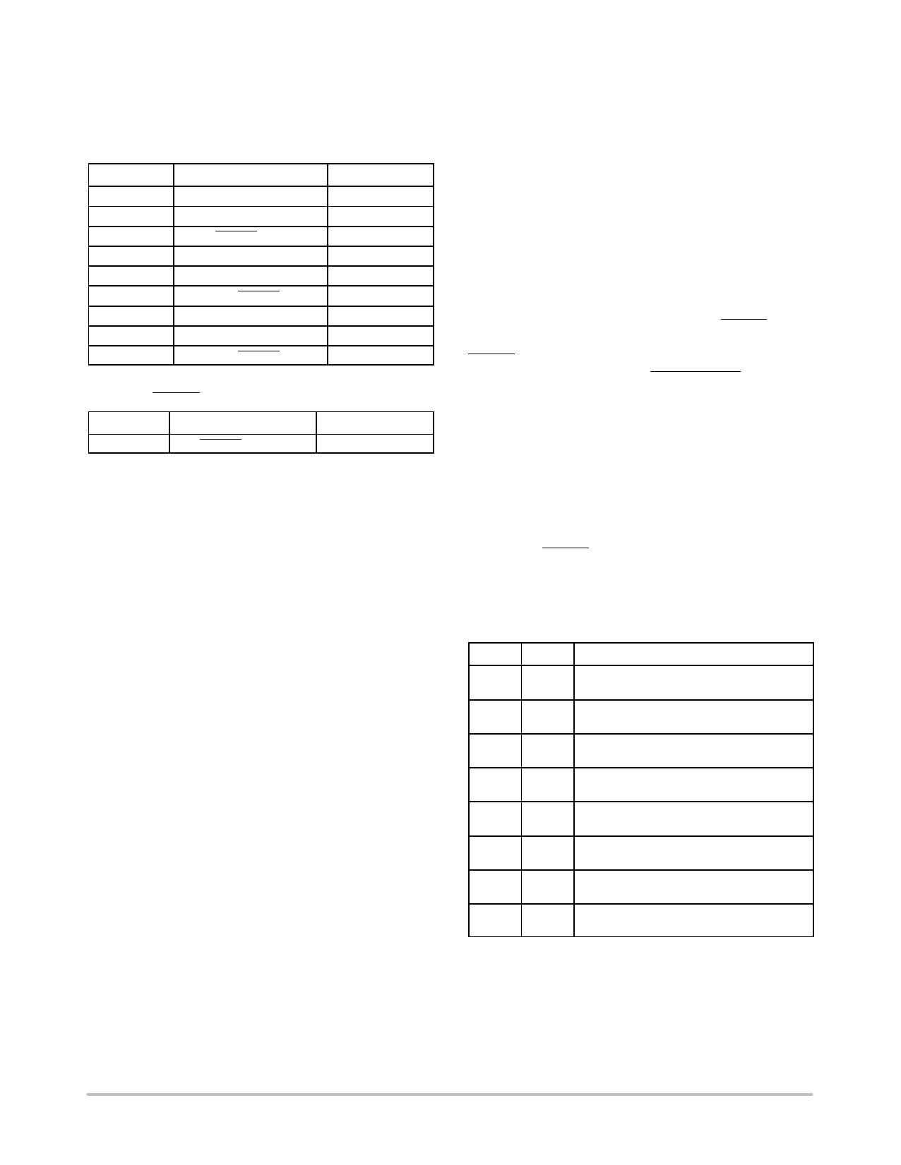
8−Bit Limits
The following is a list of all the 8−bit limits on the
ADM1034:
Table 11. Temperature Limit Registers
Register
Description
0x0B
0x0C
0x0D
0x0E
0x0F
0x10
0x11
0x12
0x13
Local High Limit
Local Low Limit
Local THERM Limit
Remote 1 High Limit
Remote 1 Low Limit
Remote 1 THERM Limit
Remote 2 High Limit
Remote 2 Low Limit
Remote 2 THERM Limit
Default
0x8B (75°C)
0x54 (20°C)
0x95 (85°C)
0x8B (75°C)
0x54 (20°C)
0x95 (85°C)
0x8B (75°C)
0x54 (20°C)
0x95 (85°C)
Table 12. THERM Limit Registers
Register
Description
0x19
THERM % Limit
Default
0xFF default
Out−of−Limit Comparisons
The ADM1034 measures all parameters in a round−robin
format and sets the appropriate status bit for out−of limit
conditions. Comparisons are made differently, depending
on whether the measured value is compared to a high or low
limit.
High Limit: ≥ Comparison Performed
Low Limit: < Comparison Performed
Analog Monitoring Cycle Time
The analog monitoring cycle time begins on powerup, or,
if monitoring has been disabled, by writing a 1 to the
monitor/ STBY bit of Configuration Register 1, (Address
0x01). The ADC measures each one of the analog inputs in
turn; as each measurement is completed, the result is
automatically stored in the appropriate value register. The
round−robin monitoring cycle continues unless it is disabled
by writing a 0 to the monitor/STBY bit (Bit 0) of
Configuration Register 1 (Address 0x01).
The ADC performs round−robin conversions and takes 11
ms for the local temperature measurement and 32 ms for
each remote temperature measurement with averaging
enabled.
The total monitoring cycle time for the average
temperatures is therefore nominally
(2 32) ) 11 + 75 ms
(eq. 2)
Once the conversion time elapses, the round robin starts
again. For more information, refer to the Conversion Rate
Register section.
Fan TACH measurements take place in parallel and are
not synchronized with the temperature measurements in any
way.
Status Registers
The results of limit comparisons are stored in the status
registers. A 1 represents an out−of−limit measurement; a 0
represents an in−limit measurement. The status registers are
located at Addresses 0x4F to 0x51.
If the measurement is outside its limits, the corresponding
status register bit is set to 1. It remains set at 1 until the
measurement falls back within its limits and it is read or until
an ARA is completed.
Poll the state of the various measurements by reading the
status registers over the serial bus. If Bit 0 (ALERT low) of
Status Register 3 (Address 0x51) is set, this means that the
ALERT output has been pulled low by the ADM1034.
Pin 14 can be configured as a SMBusALERT output. This
automatically notifies the system supervisor of an
out−of−limit condition. Reading the status register clears the
status bit as long as the error condition is gone.
Status register bits are sticky. Whenever a status bit is set
due to an out−of−limit condition, it remains set even after the
triggering event has gone. The only way to clear the status
bit is to read the status register (after the event has gone).
Interrupt mask registers (Reg. 0x08, Reg. 0x09, Reg. 0x0A)
allow individual interrupt sources to be masked from
causing an ALERT. However, if one of these masked
interrupt sources goes out of limit, its associated status bit is
set in the status register.
Table 13. Interrupt Status Register 1 (Reg. 0x4F)
Bit # Name
Description
7
LH 1 = Local high temperature limit has been
exceeded.
6
LL
1 = Local low temperature limit has been
exceeded.
5
R1H 1 = Remote 1 high temperature limit has
been exceeded.
4
R1L 1 = Remote 1 low temperature limit has
been exceeded.
3
R1D 1 = Remote 1 diode error; indicates an
open or short on the D1+/D1− pins.
2
R2H 1 = Remote 2 high temperature limit has
been exceeded.
1
R2L 1 = Remote 2 low temperature limit has
been exceeded.
0
R2D 1 = Remote 2 diode error; indicates an
open or short on the D2+/D2− pins.
http://onsemi.com
17
Share Link: 