APT7846 查看數據表(PDF) - Anpec Electronics
零件编号
产品描述 (功能)
生产厂家
APT7846 Datasheet PDF : 15 Pages
| |||
APT7846
TEMPERATURE MEASUREMENT
The temperature measurement technique used in the
APT7846 relies on the characteristics of a semicon-
ductor junction operation at a fixed current level. The
forward bipolar transistor voltage (VBE ) has a well
defined characteristic versus temperature.
If you got 25°C value of the VBE voltage then mea-
sured ambient temperature to monitor the voltage
variance.
There are two mode to measure temperature. The
Temp 0 requires calibration at a known temperature
, but only requires a single reading to predict the am-
bient temperature. The PENIRQ bipolar transistor is
used during this measurement , the A/D with an ad-
dress of A2=0 , A1=0 and A0=0 (see Table I and
Figure 6). This voltage is typically 600mV at +25°C ,
with a 20µA current through it. The TC of tempera-
ture Temp 0 is very consistent at 2.1 mV/°C. Catch
the bipolar transistor voltage on room temperature ,
in memory , for calibration purposes by the user.
The Temp 1 requires two steps to measure
temperature.
First step read Temp 0 voltage. Second step read
address of A2=1 , A1=1 , and A0=1 , with an 82 times
large current.
The voltage difference between the Temp 0 and
Temp 1 conversion using 82 times the bias.
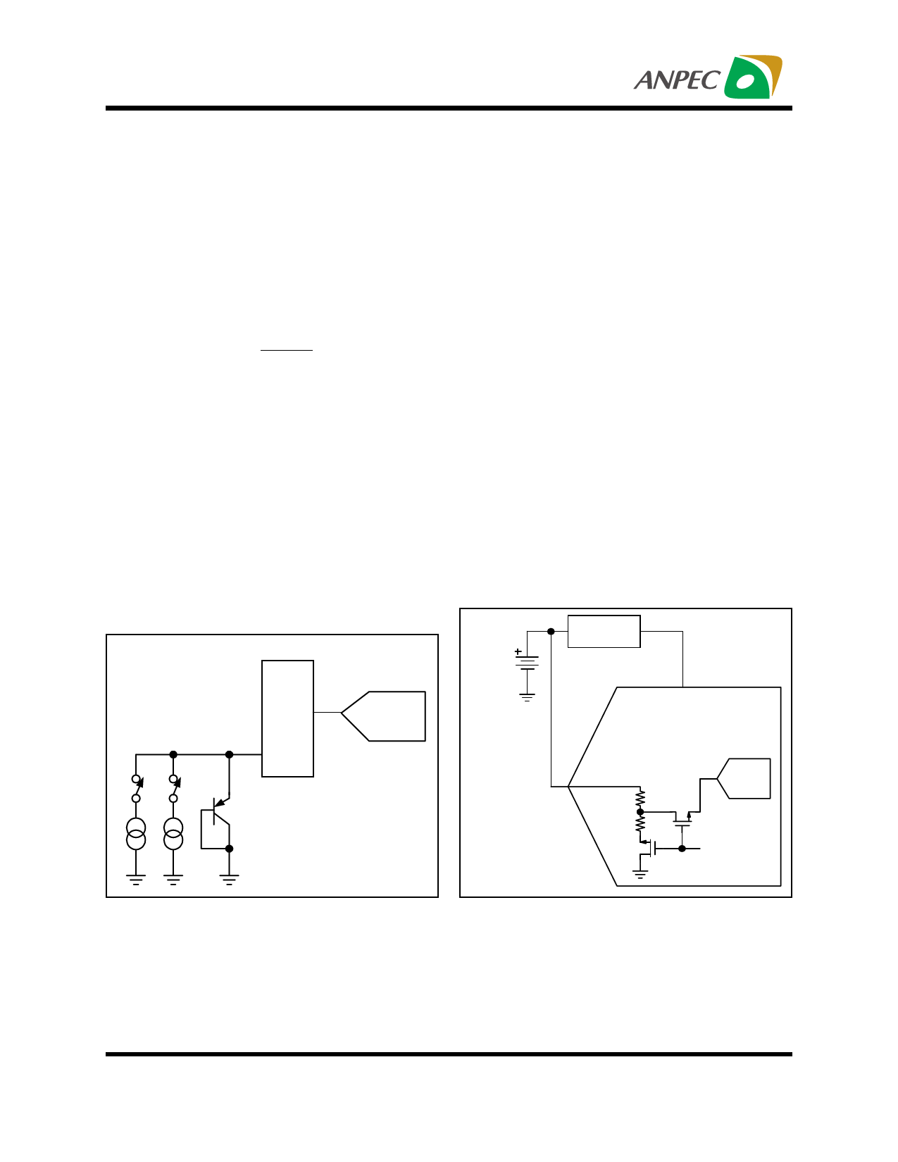
MUX
A/D
Converter
Current will be represented by kT/q ∗ ln (N) , where N
is the current ratio = 82 , k = Boltzmanns constant
(1.38054 ∗ 10e23 electrons volts/degrees Kelvin) ,
q = the electron charge (1.602189 ∗ 10e19 C) , and
T = the temperature in degrees Kelvin. The resultant
equation for solving for °K is :
°K = q ∗ ∆V / ( k ∗ In ( N ) )
(1)
where , ∆V = V( Ι82 ) V ( Ι1 ) ( mV )
∴ °K = 2.30 ∆V ( °K / mV )
°C = 2.30 ∆V ( mV ) 273 °K
BATTERY MEASUREMENT
An added feature of the APT7846 is the ability to
monitor the battery voltage , as shown in Figure7.
The battery voltage can vary from 0.5V to 6V , while
maintaining the voltage to the APT7846 at 2.7V ,
3.3V , etc. The input voltage (VBAT ) is divided down
by 4 so that a 6.0V battery voltage is represented as
1.5V to the ADC. This simplifies the multiplexer and
control logic. In order to minimize the power con-
sumption , the divider is only ON during the samling
of DIN to A2=0 , A1=1 , and A0=0. Tables I and II
show the relationship between the control bits and
configuration of the APT7846.
Battery
0.5V
to
6.0V
DC/DC
Converter
Vcc
VBAT
0.125V to 1.5V
7.5kΩ
2.5kΩ
FIGURE 6. Functional Block Diagram of Tempera- FIGURE 7. Battery Measurement Functional Block
ture Measurement Mode..1/URE
Diagram.
Copyright ANPEC Electronics Corp.
9
Rev. A.6 - Dec., 2001
www.anpec.com.tw
Share Link: 