LA4663 查看數據表(PDF) - SANYO -> Panasonic
零件编号
产品描述 (功能)
生产厂家
LA4663 Datasheet PDF : 10 Pages
| |||
LA4663
External Components
C1 and C2
• These are input coupling capacitors, and we recommend that values under 4.7 µF be used. The LA4663 uses a zero
bias type input circuit, and the input pin potential is about zero volts. Determine the polarity orientation of these
capacitors based on the DC current from the circuit connected to the LA4663 front end.
If the potential difference between across the + and – leads on the input capacitors is large, the charge time for the
input capacitors can be reduced by using as small a value as possible without causing degradation of the low band
frequency characteristics. This will shorten the time required to reach stable operation when power is first applied.
C3 *1
• This capacitor functions both as a ripple filter and as the amplifier starting time capacitor. We recommend a value of
47 µF. When the recommended value is used, the BTL SVRR between outputs will be about 63 dB, and that between
the outputs and ground will be about 47 dB. (These are values are for reference purposes.) Similarly, the starting time
(the time between the point power is first applied and the point an output is generated) will be around 0.6 to 0.7
seconds.
C4 and R1 *2
• These form an CR circuit used for muting function smoothing. C4 is required even if the muting function is not used.
C5
• Power supply capacitor
C6 to C9 and R2 to R5
• These components for oscillation prevention CR circuits. We recommend the use of polyester film capacitors (Mylar
capacitors) with excellent temperature characteristics for C6 through C9. (R2 to R5 should all be 2.2-Ω 1/4-W
resistors.)
Notes: 1. Starting time
• The LA4663 includes a built-in starting time circuit. The starting time can be varied somewhat by modifying
the value of the external capacitor connected to pin 1. With the recommended value of 47 µF, the starting time
will be between 0.6 and 0.7 second (although this will vary with the supply voltage, VCC) and this time can be
lengthened to about 0.9 second by inserting a 10 µF capacitor in parallel.
• We do not recommend using a value smaller than the recommended value for the pin 1 capacitor, since that
could result in reducing the SVRR with respect to ground.
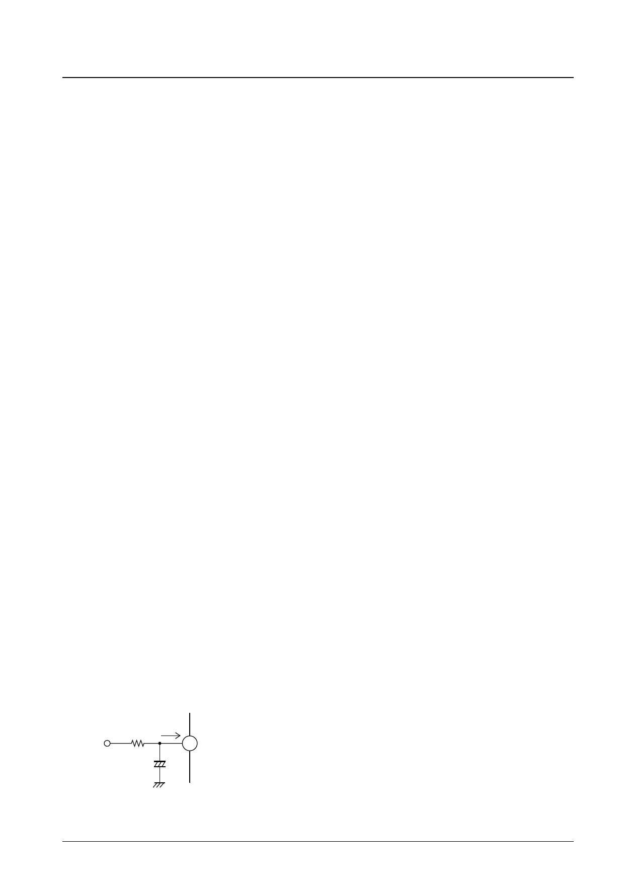
2. Signal muting function
• When the recommended CR circuit (10 µF and 22 kΩ) is connected to pin 6, the signal muting function can be
turned on, and a muting function with minimal impulse noise applied by applying a voltage of 5V.
• The CR circuit determines the attack and recovery times for smoothing function. Note that this 10-µF capacitor
is required even when the signal muting function is not used, since it is also used for smoothing after the
starting time has elapsed.The influx current to pin 6 when this external resistor has a value of
22 kΩ will be about 170 µA when the applied voltage is +5
V. Although it is possible to modify the value of this resistor
if a different applied voltage or if the capacity of the
+5 V 22 kΩ
I
6 About 1.56 V
microcontroller required it, it is possible for the level of the
impulse noise associated with the muting function to increase
+
10 µF –
if the pin 6 influx current becomes excessive. Be sure to take
this influx current into account if the value of this resistor is
modified.
A10631
No. 5905-6/10
Share Link: 