PCF8575 查看數據表(PDF) - NXP Semiconductors.
零件编号
产品描述 (功能)
生产厂家
PCF8575 Datasheet PDF : 24 Pages
| |||
Philips Semiconductors
Remote 16-bit I/O expander for I2C-bus
Product specification
PCF8575
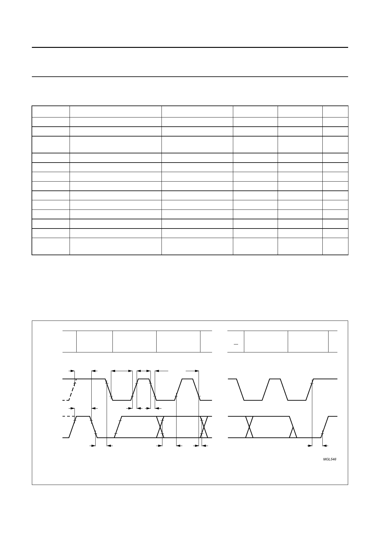
11 I2C-BUS TIMING CHARACTERISTICS
See Fig.13 and note 1.
SYMBOL
fSCL
tSW
tBUF
tSU;STA
tHD;STA
tLOW
tHIGH
tr
tf
tSU;DAT
tHD;DAT
tSU;STO
Cb
PARAMETER
SCL clock frequency
tolerable spike width on bus
BUS free time between a STOP
and START condition
START condition set-up time
START condition hold time
SCL LOW time
SCL HIGH time
SCL and SDA rise time
SCL and SDA fall time
data set-up time
data hold time
STOP condition set-up time
capacitive load represented by
each bus line
CONDITIONS
note 2
note 3
note 3
MIN.
−
−
1.3
0.6
0.6
1.3
0.6
20 + 0.1Cb
20 + 0.1Cb
100
0
0.6
−
MAX.
400
50
−
−
−
−
−
300
300
−
−
−
400
UNIT
kHz
ns
µs
µs
µs
µs
µs
ns
ns
ns
ns
µs
pF
Notes
1. All the timing values are valid within the operating supply voltage and ambient temperature range and refer to VIL
and VIH with an input voltage swing of VSS to VDD.
2. The device inputs SDA and SCL are filtered and will reject spikes on the bus lines of widths less than tSW(max).
3. The rise and fall times specified here refer to the driver device (PCF8575) and are part of the general fast I2C-bus
specification when PCF8575 asserts an acknowledge on SDA, the minimum fall time is 20 ns + 0.1Cb.
handbook, full pagewidth
PROTOCOL
START
CONDITION
(S)
BIT 7
MSB
(A7)
BIT 6
(A6)
tSU;STA
SCL
tLOW tHIGH
1/fSCL
tBUF
tr
tf
SDA
BIT 0
LSB
(R/W)
ACKNOWLEDGE
(A)
STOP
CONDITION
(P)
tHD;STA
tSU;DAT
tHD;DAT
Fig.13 I2C-bus timing diagram.
tSU;STO
MGL546
1999 Apr 07
15
Share Link: 