RC5051 查看數據表(PDF) - Fairchild Semiconductor
零件编号
产品描述 (功能)
生产厂家
RC5051
Fairchild Semiconductor

RC5051 Datasheet PDF : 16 Pages
| |||
RC5051
PRODUCT SPECIFICATION
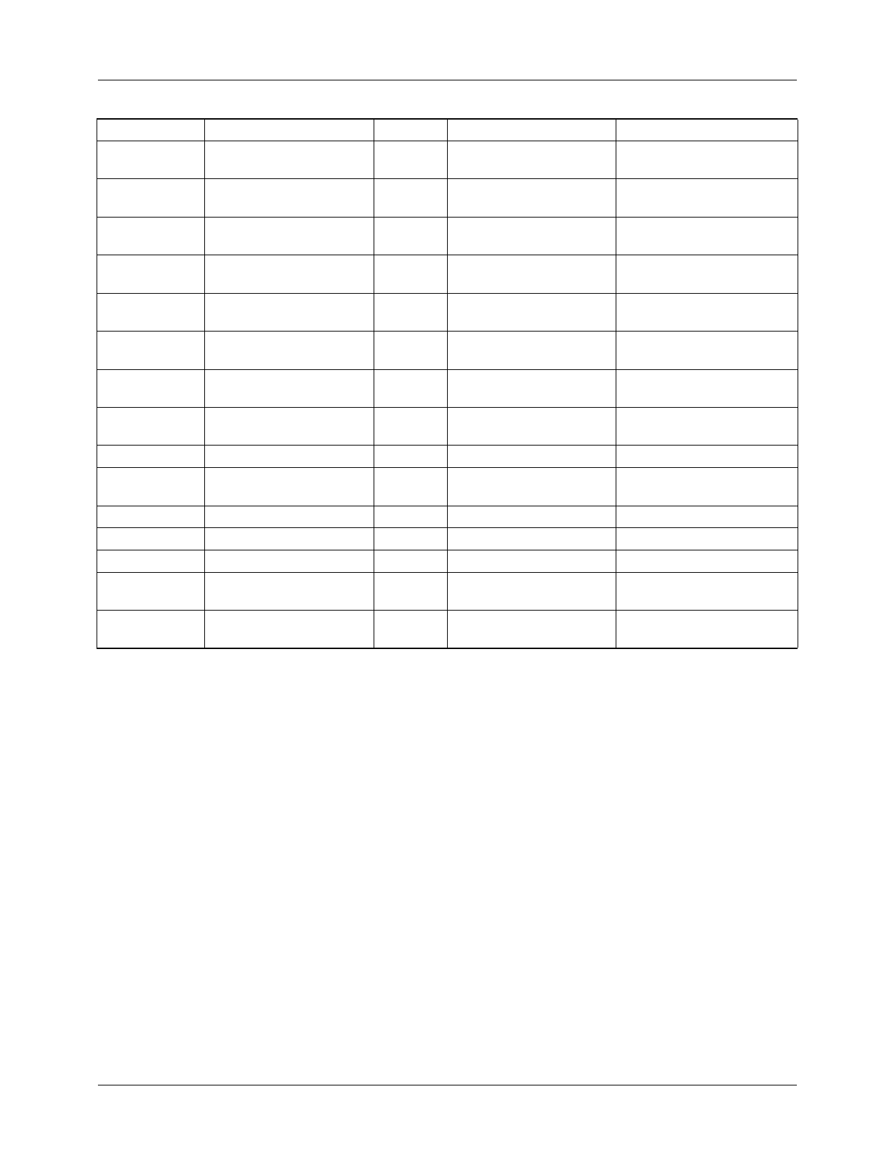
Table 2. RC5051 Application Bill of Materials for Intel Pentium II Processors
Reference
Manufacturer Part #
Quantity Description
Requirements/Comments
C1–3, C6–C8 Panasonic
ECU-V1H104ZFX
6
100nF, 50V Capacitor
C4–5
Panasonic
ECU-V1C105ZFX
2
1µF, 16V Capacitor
Cext
Panasonic
ECU-V1H101JCG
1
100pF Capacitor
5%, C0G
CIN
Sanyo
10MV1200GX
*
1200µF, 10V Electrolytic IRMS = 2A
COUT
Sanyo
6MV1500GX
*
1500µF, 6.3V Electrolytic ESR < 44mΩ
D1
Motorola
1N4735A
1
6.2V Zener Diode
D2
Motorola
1N5820
1
3A Schottky Diode
L1
Skynet
320-6110
1
2.5µH, 11A Inductor
DCR ~ 6mΩ
See Note 1.
L2
Any
1
2.3µH, 15A inductor
DCR ~ 3mΩ
Q1–2
R1
Fairchild
FDP6030L or FDB6030L
Any
2
N-Channel MOSFET
RDS(ON) = 20mΩ @
(TO-220 or TO-263)
VGS = 4.5V See Note 2
1
47Ω
R2-3
Any
2
4.7Ω
R4
Any
1
10KΩ
RSENSE
Fairchild
RC10-XX*
1
CuNi Alloy Wire Resistor
U1
Fairchild
RC5051M
1
DC/DC Controller
* See Table 3.
Notes:
1. Inductor L1 is recommended to isolate the 5V input supply from noise generated by the MOSFET switching, and to comply
with Intel dl/dt requirements. L1 may be omitted if desired.
2. For 14.2A designs using the FDP6030L MOSFETs, heatsinks with thermal resistance ΘSA < 20°C/W should be used. For
details and a spreadsheet on MOSFET selections, refer to Applications Bulletin AB-8.
8
REV. 1.0.4 4/2/01
Share Link: