TDA7492P 查看數據表(PDF) - STMicroelectronics
零件编号
产品描述 (功能)
生产厂家
TDA7492P Datasheet PDF : 26 Pages
| |||
TDA7492P
Applications information
6.2
Gain setting
The gain of the TDA7492P is set by the two inputs, GAIN0 (pin 30) and GAIN1 (pin31).
Internally, the gain is set by changing the feedback resistors of the amplifier.
Table 7. Gain settings
GAIN0
0
0
0
1
1
0
1
1
GAIN1
Nominal gain, Gv (dB)
21.6
27.6
31.1
33.6
6.3
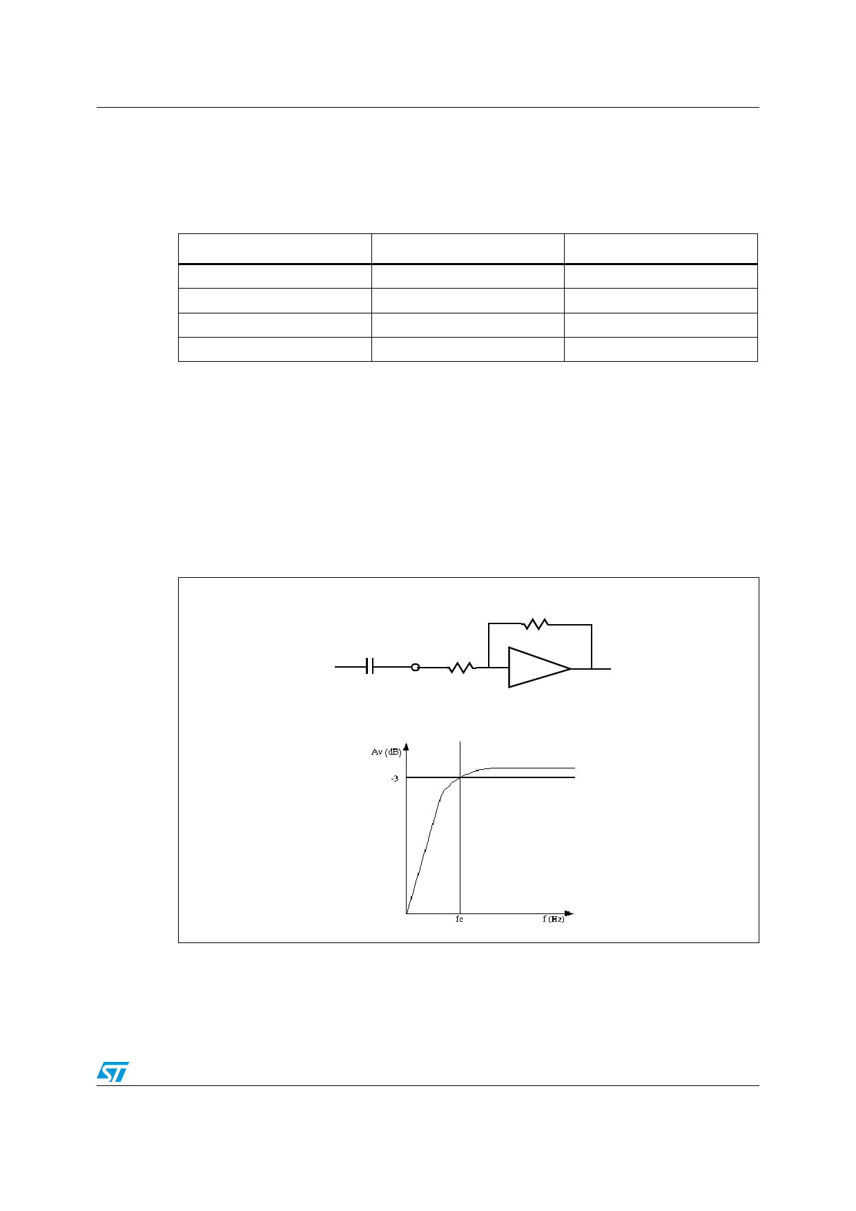
Input resistance and capacitance
The input impedance is set by an internal resistor Ri = 60 kΩ (typical). An input capacitor
(Ci) is required to couple the AC input signal.
The equivalent circuit and frequency response of the input components are shown in
Figure 23. For Ci = 470 nF the high-pass filter cutoff frequency is below 20 Hz:
fc = 1 / (2 * π * Ri * Ci)
Figure 23. Device input circuit and frequency response
Rf
Input
signal
Ci
Input Ri
pin
Doc ID 15068 Rev 5
19/26
Share Link: 