UEI25 查看數據表(PDF) - Murata Manufacturing
零件编号
产品描述 (功能)
生产厂家
UEI25 Datasheet PDF : 23 Pages
| |||
UEI25 Series
Single Output Isolated 25-Watt DC/DC Converters
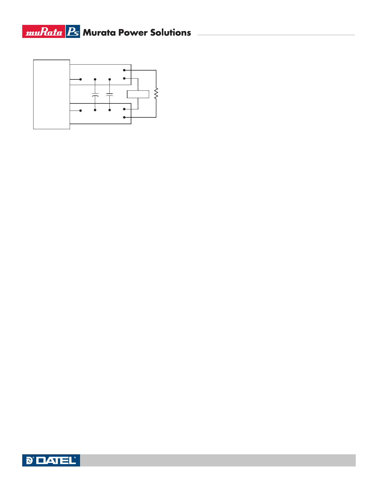
+OUTPUT
COPPER STRIP
C1
C2
SCOPE
RLOAD
−OUTPUT
COPPER STRIP
C1 = 1μF CERAMIC
C2 = 10μF LOW ES
LOAD 2-3 INCHES (51-76mm) FROM MODULE
Figure 3. Measuring Output Ripple and Noise (PARD)
the ground return of the load circuit. You can however use the positive output
(+Output) as the ground return to effectively reverse the output polarity.
Minimum Output Loading Requirements
These converters employ a synchronous rectifier design topology. All models
regulate within specification and are stable from 0% load to full load conditions,
unless otherwise specified. Operation under no load will not damage the con-
verter but might, however, slightly increase regulation, output ripple, and noise.
Thermal Shutdown
To protect against thermal over-stress, these converters include thermal shut-
down circuitry. If environmental conditions cause the temperature of the DC/
DC’s to rise above the Operating Temperature Range up to the shutdown tem-
perature, an on-board electronic temperature sensor will power down the unit.
When the temperature decreases below the turn-on threshold, the converter
will automatically restart. There is a small amount of hysteresis to prevent
rapid on/off cycling. CAUTION: If you operate too close to the thermal limits, the
converter may shut down suddenly without warning. Be sure to thoroughly test
your application to avoid unplanned thermal shutdown.
Temperature Derating Curves
The graphs in the performance data section illustrate typical operation under a
variety of conditions. The Derating curves show the maximum continuous ambient
air temperature and decreasing maximum output current which is acceptable under
increasing forced airflow measured in Linear Feet per Minute (“LFM”). Note that
these are AVERAGE measurements. The converter will accept brief increases in tem-
perature and/or current or reduced airflow as long as the average is not exceeded.
Note that the temperatures are of the ambient airflow, not the converter it-
self which is obviously running at higher temperature than the outside air. Also
note that “natural convection” is defined as very low flow rates which are not
using fan-forced airflow. Depending on the application, “natural convection” is
usually about 30-65 LFM but is not equal to still air (0 LFM).
Murata Power Solutions makes Characterization measurements in a closed
cycle wind tunnel with calibrated airflow. We use both thermocouples and an
infrared camera system to observe thermal performance. As a practical matter,
it is quite difficult to insert an anemometer to precisely measure airflow in
most applications. Sometimes it is possible to estimate the effective airflow if
you thoroughly understand the enclosure geometry, entry/exit orifice areas and
the fan flowrate specifications.
CAUTION: If you exceed these Derating guidelines, the converter may have
an unplanned Over Temperature shut down. Also, these graphs are all collected
near Sea Level altitude. Be sure to reduce the derating for higher altitude.
Output Overvoltage Protection (OVP)
This converter monitors its output voltage for an over-voltage condition using
an on-board electronic comparator. The signal is optically coupled to the pri-
mary side PWM controller. If the output exceeds OVP limits, the sensing circuit
will power down the unit, and the output voltage will decrease. After a time-out
period, the PWM will automatically attempt to restart, causing the output volt-
age to ramp up to its rated value. It is not necessary to power down and reset
the converter for this automatic OVP-recovery restart.
If the fault condition persists and the output voltage climbs to excessive
levels, the OVP circuitry will initiate another shutdown cycle. This on/off cycling
is referred to as “hiccup” mode.
Output Fusing
The converter is extensively protected against current, voltage and temperature
extremes. However, your application circuit may need additional protection. In the
extremely unlikely event of output circuit failure, excessive voltage could be applied
to your circuit. Consider using an appropriate external protection.
Output Current Limiting
As soon as the output current increases to approximately its overcurrent limit,
the DC/DC converter will enter a current-limiting mode. The output voltage will
decrease proportionally with increases in output current, thereby maintaining a
somewhat constant power output. This is commonly referred to as power limiting.
Current limiting inception is defined as the point at which full power falls
below the rated tolerance. See the Performance/Functional Specifications.
Note particularly that the output current may briefly rise above its rated value.
This enhances reliability and continued operation of your application. If the
output current is too high, the converter will enter the short circuit condition.
Output Short Circuit Condition
When a converter is in current-limit mode, the output voltage will drop as
the output current demand increases. If the output voltage drops too low, the
magnetically coupled voltage used to develop PWM bias voltage will also drop,
thereby shutting down the PWM controller. Following a time-out period, the
PWM will restart, causing the output voltage to begin rising to its appropriate
value. If the short-circuit condition persists, another shutdown cycle will initi-
ate. This on/off cycling is called “hiccup mode.” The hiccup cycling reduces the
average output current, thereby preventing excessive internal temperatures.
Trimming the Output Voltage
The Trim input to the converter allows the user to adjust the output voltage over
the rated trim range (please refer to the Specifications). In the trim equations
and circuit diagrams that follow, trim adjustments use a single fixed resistor
connected between the Trim input and either Vout pin. Trimming resistors should
have a low temperature coefficient (±100 ppm/°C or less) and be mounted close
to the converter. Keep leads short. If the trim function is not used, leave the trim
unconnected. With no trim, the converter will exhibit its specified output voltage
accuracy.
There are two CAUTIONs to observe for the Trim input:
www.murata-ps.com
MDC_UEI25W.B03 Page 20 of 23
Share Link: 