DS1775R1TR 查看數據表(PDF) - Maxim Integrated
零件编号
产品描述 (功能)
生产厂家
DS1775R1TR Datasheet PDF : 15 Pages
| |||
DS1775
Digital Thermometer and Thermostat in SOT23
Accordingly, the following bus conditions have been
defined:
Bus not busy: Both data and clock lines remain HIGH.
Start data transfer: A change in the state of the data
line, from HIGH to LOW, while the clock is HIGH, defines
a START condition.
Stop data transfer: A change in the state of the data line,
from LOW to HIGH, while the clock line is HIGH, defines
the STOP condition.
Data valid: The state of the data line represents valid
data when, after a START condition, the data line is stable
for the duration of the HIGH period of the clock signal.
The data on the line must be changed during the LOW
period of the clock signal. There is one clock pulse per
bit of data.
Each data transfer is initiated with a START condition and
terminated with a STOP condition. The number of data
bytes transferred between START and STOP conditions
is not limited, and is determined by the master device.
The information is transferred byte-wise and each receiv-
er acknowledges with a ninth bit.
Within the bus specifications a standard mode (100kHz
clock rate) and a fast mode (400kHz clock rate) are
defined. The DS1775 works in both modes.
Acknowledge: Each receiving device, when addressed,
is obliged to generate an acknowledge after the reception
of each byte. The master device must generate an extra
clock pulse which is associated with this acknowledge bit.
A device that acknowledges must pull down the SDA line
during the acknowledge clock pulse in such a way that
the SDA line is stable LOW during the HIGH period of the
acknowledge related clock pulse. Of course, setup and
hold times must be taken into account. A master must
signal an end of data to the slave by not generating an
acknowledge bit on the last byte that has been clocked
out of the slave. In this case, the slave must leave the
data line HIGH to enable the master to generate the
STOP condition.
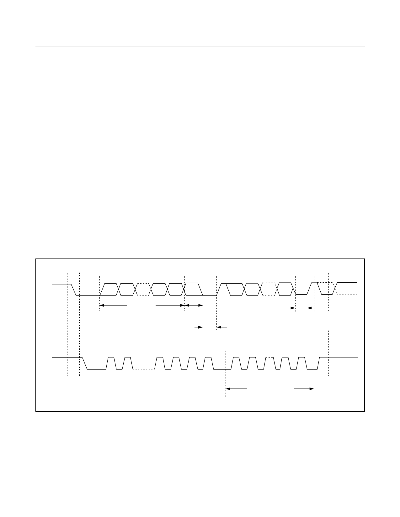
SDA
SCL
START
CONDITION
MSB
SLAVE
ADDRESS
R/W
DIRECTION
BIT
ACKNOWLEDGEMENT
SIGNAL FROM
RECEIVER
ACKNOWLEDGEMENT
SIGNAL FROM
RECEIVER
1
2
6
7
8
9
ACK
1
2
3–8 8
9
ACK
REPEATED IF
MORE BYTES ARE
TRANSFERRED
STOP CONDITION
OR REPEATED
START CONDITION
Figure 3. Data Transfer on 2-Wire Serial Bus
www.maximintegrated.com
Maxim Integrated │ 10
Share Link: 