DS1775R1TR 查看數據表(PDF) - Maxim Integrated
零件编号
产品描述 (功能)
生产厂家
DS1775R1TR Datasheet PDF : 15 Pages
| |||
DS1775
Digital Thermometer and Thermostat in SOT23
Detailed Description
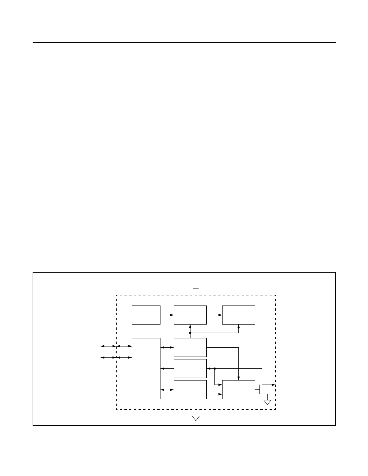
Figure 1 shows a block diagram of the DS1775. The
DS1775 consists of five major components:
1) Precision temperature sensor
2) Analog-to-digital converter
3) 2-wire interface electronics
4) Data registers
5) Thermostat comparator
The factory-calibrated temperature sensor requires no
external components. Upon power-up, the DS1775 begins
temperature conversions with the default resolution of 9
bits (0.5°C resolution). The host can periodically read the
value in the temperature register, which contains the last
completed conversion. As conversions are performed in
the background, reading the temperature register does
not affect the conversion in progress.
In power-sensitive applications, the user can put the
DS1775 into a shutdown mode, under which the sensor
complete and store the conversion in progress and revert
to a low-power standby state. In applications where small
incremental temperature changes are critical, the user
can change the conversion resolution from 9 bits to 10,
11, or 12. Each additional bit of resolution approximately
Block Diagram
doubles the conversion time. This is accomplished by
programming the configuration register. The configuration
register defines the conversion state, thermometer resolu-
tion/conversion time, active state of the thermostat output,
number of consecutive faults to trigger an alarm condition,
and the method to terminate an alarm condition.
The user can also program overtemperature (TOS) and
undertemperature (THYST) setpoints for thermostatic
operation. The power-up state of TOS is +80°C and that
for THYST is +75°C. The result of each temperature con-
version is compared with the TOS and THYST setpoints.
The DS1775 offers two modes for temperature control,
the comparator mode and the interrupt mode. This allows
the user the flexibility to customize the condition that
would generate and clear a fault condition. Regardless of
the mode chosen, the O.S. output becomes active only
after the measured temperature exceeds the respective
trip-point a consecutive number of times; the number of
consecutive conversions beyond the limit to generate an
O.S. is programmable. The power-up state of the DS1775
is in the comparator mode with a single fault generating
an active O.S.
Digital data is written to/read from the DS1775 via a
2-wire interface, and all communication is MSb first.
2.7V - 5.5V
SUPPLY
PRECISION
REFERENCE
VDD
OVERSAMPLING
MODULATOR
DIGITAL
DECIMATOR
SDA
TO
CPU
SCL
CONFIGURATION
REGISTER
I/O CONTROL
INPUT SENSE
THERMOMETER
REGISTER
THERMOSTAT
REGISTERS
GND
DS1775
O.S.
THERMOSTAT
COMPARATOR
Figure 1. Block Diagram
www.maximintegrated.com
Maxim Integrated │ 5
Share Link: 