DS1775R4U 查看數據表(PDF) - Maxim Integrated
零件编号
产品描述 (功能)
生产厂家
DS1775R4U Datasheet PDF : 15 Pages
| |||
DS1775
Digital Thermometer and Thermostat in SOT23
The DS1775 powers up with the temperature register
selected. If the host wishes to change the data pointer, it
simply addresses the DS1775 in the write mode (R/W=
0), receives an acknowledge, and writes the 8 bits that
correspond to the new desired location. The last pointer
location is always maintained so that consecutive reads
from the same register do not require the host to always
provide a pointer address. The only exception is at power-
up, in which case the pointer is always set to 00h, the
temperature register. The pointer address must always
precede data in writing to a register, regardless of which
address is currently selected. See the 2-Wire Serial Data
Bus section for details of the 2-wire bus protocol.
Configuration Register Programming
The configuration register is accessed if the DS1775
pointer is currently set to the 01h location. Writing to or
reading from the register is determined by the R/W bit of
the 2-wire control byte (see the 2-Wire Serial Data Bus
section). Data is read from or written to the configuration
register MSb first. The format of the register is illustrated
in Table 3. The effect each bit has on DS1775 functionality
is described below along with the power-up state of the
bit. The user has read/write access to all bits in the con-
figuration register. The entire register is volatile, and thus
it powers up in the default state.
SD = Shutdown bit. If SD is 0, the DS1775 continuously
performs temperature conversions and stores the last
completed result in the thermometer register. If SD is
changed to 1, the conversion in progress is completed
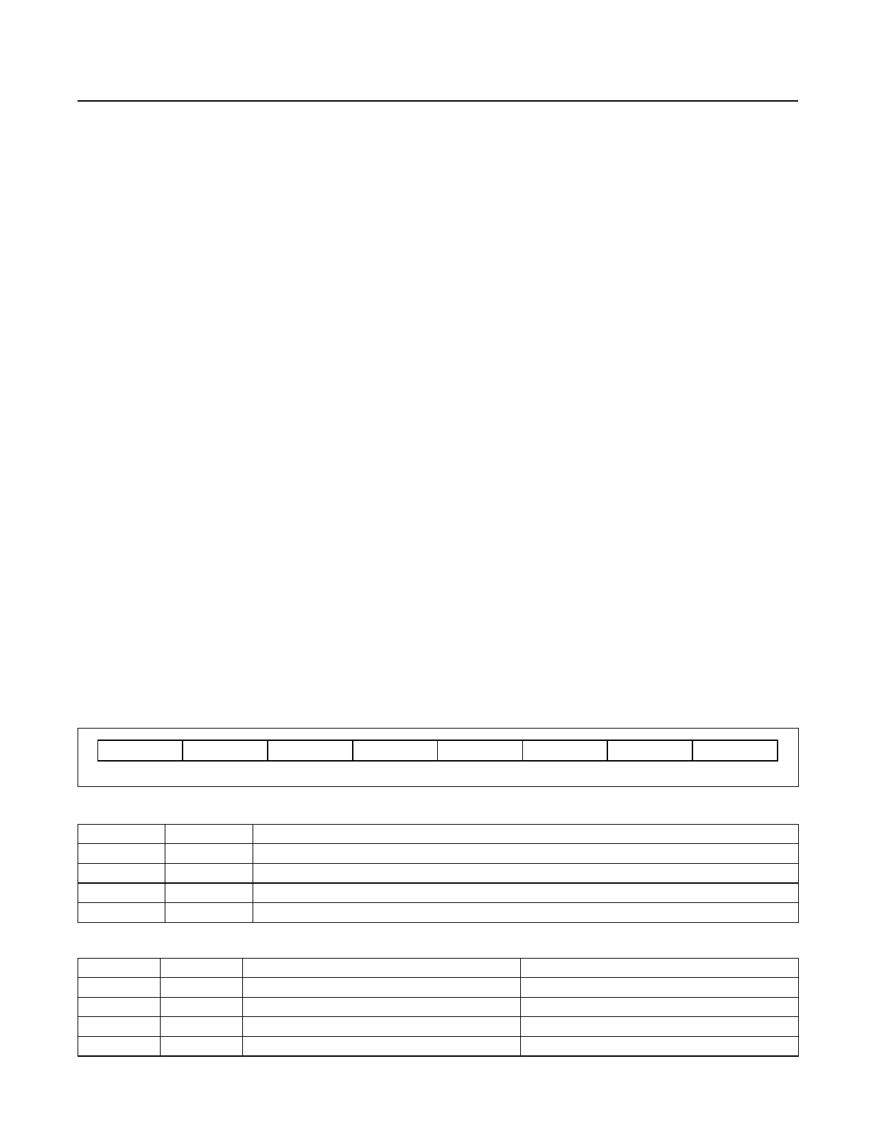
Table 3. Configuration/Status Register
and stored; then the device reverts to a low-power stand-
by mode. The O.S. output is cleared if the device is in the
interrupt mode and remains unchanged in the compara-
tor mode. The 2-wire port remains active. The power-up
default state is 0 (continuous conversion mode).
TM = Thermostat mode. If TM = 0, the DS1775 is in the
comparator mode. TM = 1 sets the device to the interrupt
mode. See the Thermostat Control section for a descrip-
tion of the difference between the two modes. The power-
up default state of the TM bit is 0 (comparator mode).
POL = O.S. Polarity Bit. If POL = 1, the active state of
the O.S. output is high. A 0 stored in this location sets the
thermostat output to an active-low state. The user has
read/write access to the POL bit, and the power-up default
state is 0 (active low).
F0, F1 = O.S. Fault Tolerance bits. The fault tolerance
defines the number of consecutive conversions returning
a temperature beyond limits is required to set the O.S.
output in an active state. This may be necessary to add
margin in noisy environments. Table 4 defines the four
settings. The DS1775 powers up with F0 = F1 = 0, such
that a single occurrence triggers a fault.
R0, R1 = Thermometer resolution bits. Table 5 defines
the resolution of the digital thermometer, based on the
settings of these two bits. There is a direct trade-off
between resolution and conversion time, as shown in the
AC Electrical Characteristics. The default state is R0 = 0
and R1 = 0 (9-bit conversions).
0
R1
R0
F1
F0
POL
TM
SD
MSb
LSb
Table 4. Fault Tolerance Configuration
F1
F0
0
0
0
1
1
0
1
1
CONSECUTIVE CONVERSIONS BEYOND LIMITS TO GENERATE FAULT
1
2
4
6
Table 5. Thermometer Resolution Configuration
R1
R0
THERMOMETER RESOLUTION (BITS)
MAX CONVERSION TIME (SECONDS)
0
0
9
0.1875
0
1
10
0.375
1
0
11
0.75
1
1
12
1.5
www.maximintegrated.com
Maxim Integrated │ 8
Share Link: 