MAX122ACAG 查看數據表(PDF) - Maxim Integrated
零件编号
产品描述 (功能)
生产厂家
MAX122ACAG Datasheet PDF : 15 Pages
| |||
MAX120/MAX122
500ksps, 12-Bit ADCs with Track/Hold
and Reference
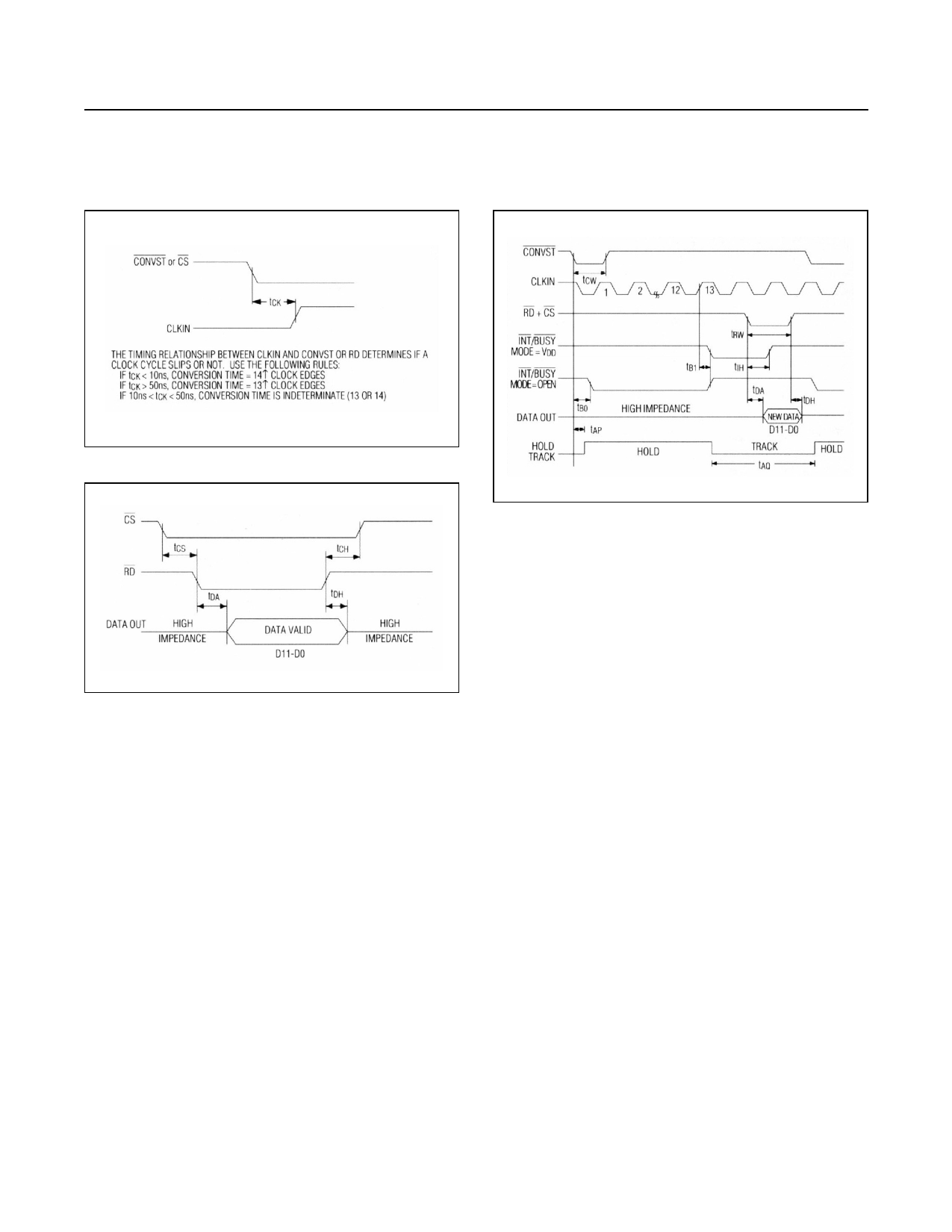
Figure 5. Clock and Control Synchronization
Figure 6. Data-Access and Bus-Relinquish Timing
Output Data Format
The conversion result is output on a 12-bit data bus with
a 75ns data-access time. The output data format is twos-
complement. Three input control signals (CS, RD, and
CONVST), the INT/BUSY converter status output, and the
12 bits of output data can interface directly to a 16-bit data
bus. See Figure 6 for data-access timing.
Timing and Control
The MAX120/MAX122 have five operational modes as
outlined in Figures 7 to 11 and discussed in the Operating
Modes section.
Full-control mode (mode 1) provides maximum control to
the user for convert start and data-read operations.
Full-control mode is for µPs with or without wait-state
capability. Stand-alone mode (mode 2) and continuous-
conversion mode (mode 5) are for systems without µPs,
Figure 7. Full-Control Mode (Mode 1)
or for µP-based systems where the ADC and the µP are
linked through first-in, first-out (FIFO) buffers or direct
memory access (DMA) ports. Slow-memory mode (mode
3) is intended for µPs that can be forced into a wait state
during the ADC’s conversion time. ROM mode (mode 4) is
for µPs that cannot be forced into a wait state.
In all five operating modes, the start of a conversion is
controlled by one of three digital inputs: CONVST, RD, or
CS. Figure 12 shows the logic equivalent for the conver-
sion circuitry. In any operating mode, CONVST must be
low for a conversion to occur. Once the conversion is in
progress, it cannot be restarted.
Read operations are controlled by RD and CS. Both of
these digital inputs must be low to read output data. The
INT/BUSY output indicates the converter’s status and
determines when the data from the most recent conver-
sion is available. The MODE input configures the INT/
BUSY output as follows:
If MODE = VDD, INT/BUSY functions as an
INTERRUPT output. In this configuration, INT/BUSY
goes low when the conversion is complete and returns
high after the conversion data has been read.
If MODE is left open or tied to DGND, INT/BUSY
functions as a BUSY output. In this case, INT/BUSY
goes low at the start of a conversion and remains low
until the conversion is complete and the data is avail-
able at D0–D11.
www.maximintegrated.com
Maxim Integrated │ 7
Share Link: 