DS17885S-3 查看數據表(PDF) - Maxim Integrated
零件编号
产品描述 (功能)
生产厂家
DS17885S-3 Datasheet PDF : 31 Pages
| |||
DS17285/DS17287/
DS17485/DS17487/
DS17885/DS17887
Detailed Description
The DS17x85 is a successor to the DS1285 real-time
clock (RTC). The device provides 18 bytes of real-time
clock/calendar, alarm, and control/status registers and 114
bytes of nonvolatile battery-backed RAM. The device also
provides additional extended RAM in either 2k/4k/8kbytes
(DS17285/DS17485/DS17885). A time-of-day alarm, six
maskable interrupts with a common interrupt output, and
a programmable square-wave output are available. It also
operates in either 24-hour or 12-hour format with an AM/
PM indicator. A precision temperature-compensated cir-
cuit monitors the status of VCC. If a primary power-supply
failure is detected, the device automatically switches to
a backup supply. The backup supply input supports a
primary battery, such as a lithium coin cell. The device is
accessed by a multiplexed address/data bus.
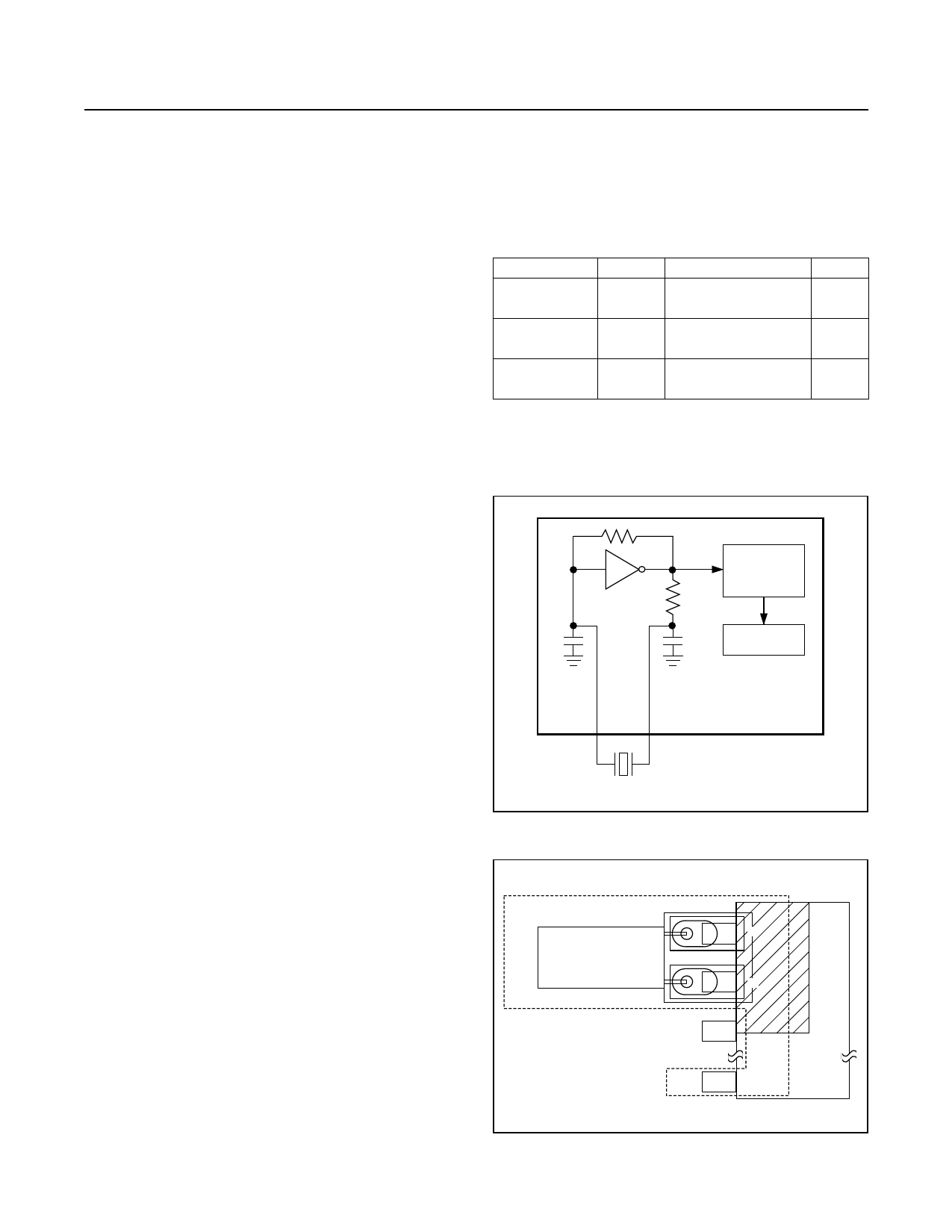
Oscillator Circuit
The DS17x85 uses an external 32.768kHz crystal. The
oscillator circuit does not require any external resistors
or capacitors to operate. Table 1 specifies several crystal
parameters for the external crystal, and Figure 2 shows
a functional schematic of the oscillator circuit. The oscil-
lator is controlled by an enable bit in the control register.
Oscillator startup times are highly dependent upon crystal
characteristics, PC board leakage, and layout. High ESR
and excessive capacitive loads are the major contributors
to long startup times. A circuit using a crystal with the
recommended characteristics and proper layout usually
starts within one second.
An external 32.768kHz oscillator can also drive the
DS17x85. In this configuration, the X1 pin is connected
to the external oscillator signal and the X2 pin is left
unconnected.
Clock Accuracy
The accuracy of the clock is dependent upon the accu-
racy of the crystal and the accuracy of the match between
the capacitive load of the oscillator circuit and the capaci-
tive load for which the crystal was trimmed. Additional
error will be added by crystal frequency drift caused by
temperature shifts. External circuit noise coupled into
the oscillator circuit may result in the clock running fast.
Figure 3 shows a typical PC board layout for isolation of
the crystal and oscillator from noise. Refer to Application
Note 58: Crystal Considerations with Dallas Real-Time
Clocks for detailed information.
Clock Accuracy (DS17287,
DS17487, and DS17887)
The encapsulated DIP (EDIP) modules are trimmed at the
factory to ±1 minute per month accuracy at 25°C.
www.maximintegrated.com
Real-Time Clocks
Table 1. Crystal Specifications* (DS17x85
Only)
PARAMETER
Nominal
Frequency
Series
Resistance
Load
Capacitance
SYMBOL MIN
fO
ESR
CL
TYP
32.768
6 or
12.5
MAX
50
UNITS
kHz
kΩ
pF
*The crystal, traces, and crystal input pins should be isolated
from RF generating signals. Refer to Application Note 58:
Crystal Considerations for Dallas Real-Time Clocks for addi-
tional specifications.
COUNTDOWN
CHAIN
CL1
CL2 RTC REGISTERS
DS17285/87
DS17485/87
DS17885/87
X1
X2
CRYSTAL
Figure 2. Oscillator Circuit Showing Internal Bias Network
LOCAL GROUND PLANE (TOP LAYER)
CRYSTAL
NOTE: AVOID ROUTING SIGNAL LINES
IN THE CROSSHATCHED AREA
(UPPER LEFT QUADRANT) OF
THE PACKAGE UNLESS THERE IS
A GROUND PLANE BETWEEN THE
SIGNAL LINE AND THE DEVICE PACKAGE.
Figure 3. Layout Example
X1
X2
GND
Maxim Integrated │ 11
Share Link: 