MAX791ESE(1995) 查看數據表(PDF) - Maxim Integrated
零件编号
产品描述 (功能)
生产厂家
MAX791ESE Datasheet PDF : 20 Pages
| |||
Microprocessor Supervisory Circuit
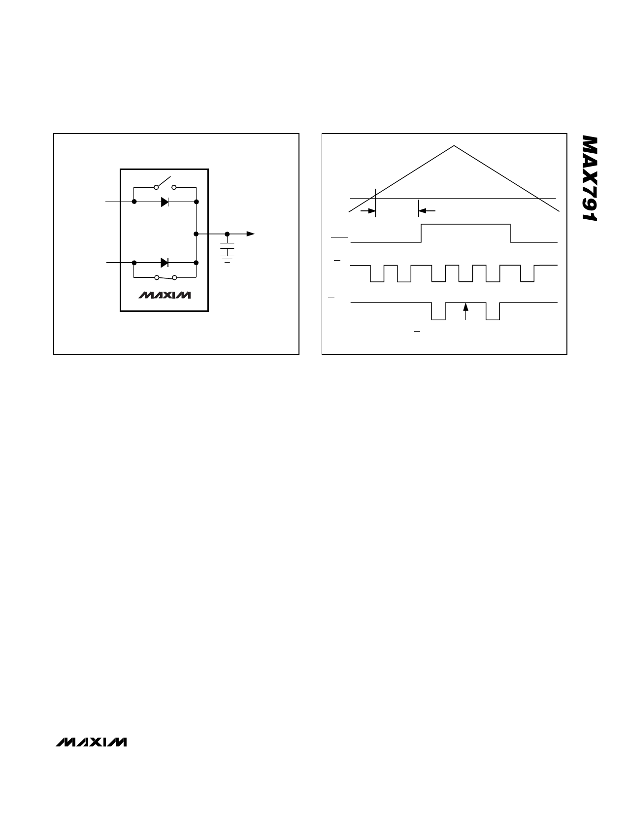
VBATT 1
VCC 3
2
VOUT
0.1µF
MAX791
Figure 10. VCC and VBATT-to-VOUT Switch
RESET
THRESHOLD
VCC
RESET
CE IN
200ms TYP
CE OUT
SECOND CE PULSE ABSENT WHEN VBATT < 2V
Figure 11. Backup-Battery Monitor Timing Diagram
Battery-Backup Mode
The MAX791 requires two conditions to switch to bat-
tery-backup mode: 1) VCC must be below the reset
threshold; 2) VCC must be below VBATT. Table 1 lists
the status of the inputs and outputs in battery-backup
mode.
Battery On Output
The Battery On (BATT ON) output indicates the status
of the internal VCC/battery-switchover comparator,
which controls the internal VCC and VBATT switches.
For VCC greater that VBATT (ignoring the small hystere-
sis effect), BATT ON typically sinks 3.2mA at 0.1V satu-
ration voltage. In battery-backup mode, this terminal
sources approximately 10µA from VOUT. Use BATT ON
to indicate battery-switchover status or to supply base
drive to an external pass transistor for higher-current
applications (see Typical Operating Circuit).
Input Supply Voltage
The Input Supply Voltage (VCC) should be a regulated
+5V. VCC connects to VOUT via a parallel diode and a
large PMOS switch. The switch carries the entire cur-
rent load for currents less than 250mA. The parallel
diode carries any current in excess of 250mA. Both the
switch and the diode have impedances less than 1Ω
each (Figure 10). The maximum continuous current is
250mA, but power-on transients may reach a maximum
of 1A.
Backup-Battery Input
The Backup-Battery Input (VBATT) is similar to VCC,
except the PMOS switch and parallel diode are much
smaller. Accordingly, the on-resistances of the diode
and the switch are each approximately 10Ω.
Continuous current should be limited to 25mA and
peak currents (only during power-up) limited to 250mA.
The reverse leakage of this input is less than 1µA over
temperature and supply voltage.
Output Supply Voltage
The Output Supply Voltage (VOUT) is internally connect-
ed to the substrate of the IC and supplies all the current
to the external system and internal circuitry. All open-
circuit outputs will, for example, assume the VOUT volt-
age in their high states rather than the VCC voltage. At
the maximum source current of 250mA, VOUT will typi-
cally be 200mV below VCC. Decouple this terminal with
a 0.1µF capacitor.
______________________________________________________________________________________ 13
Share Link: 