MAX690C 查看數據表(PDF) - Maxim Integrated
零件编号
产品描述 (功能)
生产厂家
MAX690C Datasheet PDF : 18 Pages
| |||
MAX690–MAX695
Microprocessor Supervisory Circuits
Application Hints
Other Uses of the Power-Fail Detector
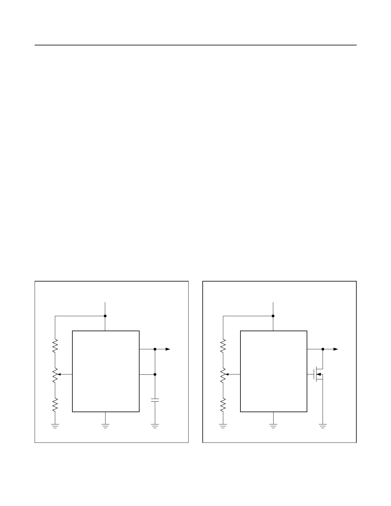
In Figure 9, the power-fail detector is used to initiate a
system reset when VCC falls to 4.85V. Since the thresh-
old of the power-fail detector is not as accurate as the
onboard reset-voltage detector, a trimpot must be used
to adjust the voltage detection threshold. Both the PFO
and RESET outputs have high sink current capability and
only 10µA of source current drive. This allows the two
outputs to be connected directly to each other in a wired
OR fashion.
The overvoltage detector circuit in Figure 10 resets the
microprocessor whenever the nominal 5V VCC is above
5.5V. The battery monitor circuit (Figure 11) shows the
status of the memory backup battery. If desired, the CE
OUT can be used to apply a test load to the battery. Since
CE OUT is forced high during the battery backup mode,
the test load will not be applied to the battery while it is in
use even if the microprocessor is not powered.
Adding Hysteresis
to the Power Fail Comparator
Since the power fail comparator circuit is noninvert-
ing, hysteresis can be added by connecting a resistor
between the PFO output and the PFI input as shown in
Figure 12. When PFO is low, resistor R3 sinks current
from the summing junction at the PFI pin. When PFO is
high, the series combination of R3 and R4 source current
into the PFI summing junction.
Alternate Watchdog Input Drive Circuits
The Watchdog feature can be enabled and disabled
under program control by driving WDI with a three-state
buffer (Figure 13). The drawback to this circuit is that a
software fault may be erroneously three-state the buffer,
thereby preventing the MAX690 from detecting that the
microprocessor is no longer working. In most cases a bet-
ter method is to extend the watchdog period rather than
disabling the watchdog. See Figure 14. When the control
input is high, the OSC SEL pin is low and the watchdog
timeout is set by the external capacitor. A 0.01µF capaci-
tor sets a watchdog timeout delay of 100s. When the
control input is low the OSC SEL pin is high, selecting
the internal oscillator. The 100ms or the 1.6s period is
chosen, depending on which diode in Figure 14 is used.
+5V
+5V
29.4kΩ
2kΩ
10kΩ
VCC
RESET
MAX690
MAX691
MAX692
PFI
MAX693
PFO
MAX694
MAX695
GND
TO µP
RESET
INPUT
35.7kΩ
2kΩ
10kΩ
VCC
RESET
MAX690
MAX691
PFI
MAX692
MAX693
PFO
MAX694
MAX695
GND
TO µP
RESET
INPUT
N-CHANNEL
Figure 9. Externally Adjustable VCC Reset Threshold
www.maximintegrated.com
Figure 10. Reset on Overvoltage or Undervoltage
Maxim Integrated │ 13
Share Link: 