MC68010R8 查看數據表(PDF) - Motorola => Freescale
零件编号
产品描述 (功能)
生产厂家
MC68010R8 Datasheet PDF : 26 Pages
| |||
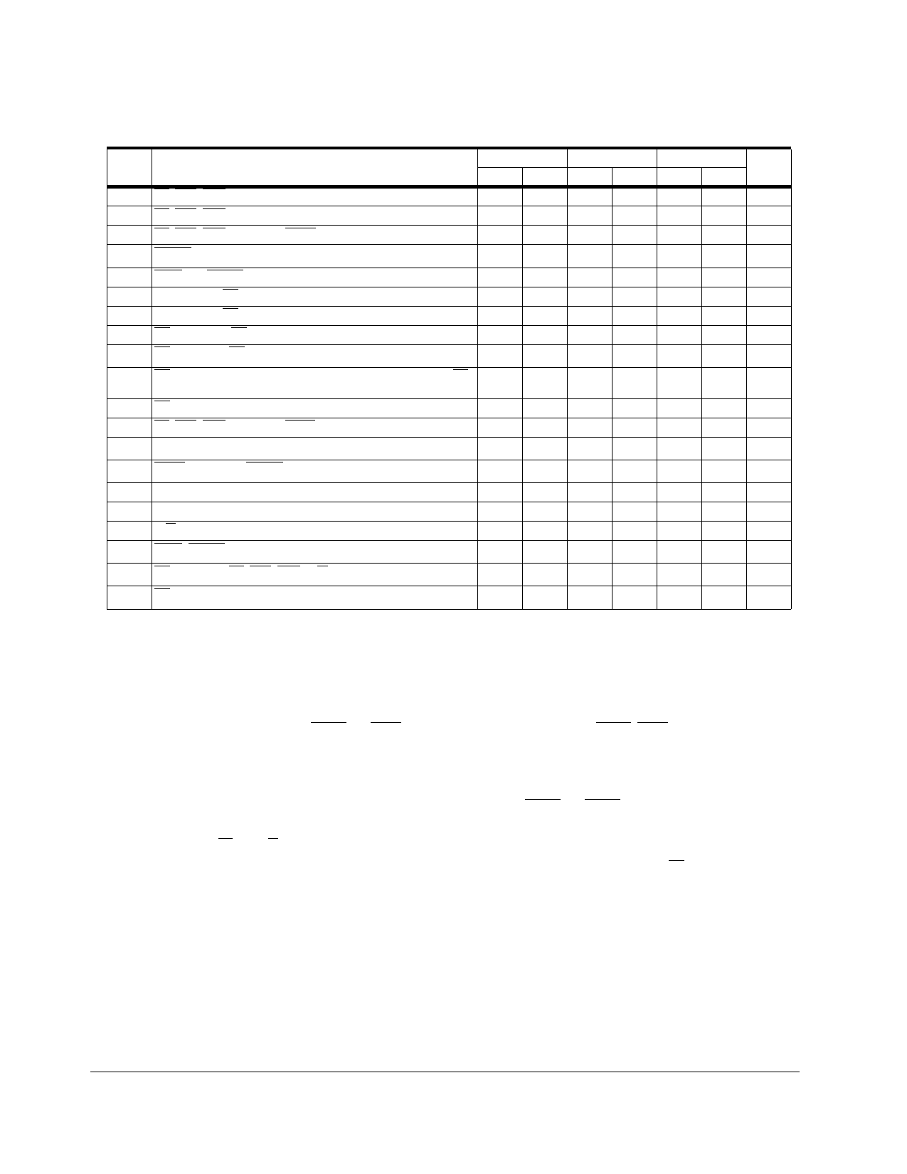
AC ELECTRICAL SPECIFICATIONS — READ AND WRITE CYCLES (Continued)
NUM
CHARACTERISTIC
29 AS, LDS, UDS Negated to Data-In Invalid (Hold Time on Read)
29A AS, LDS, UDS Negated to Data-In High Impedance (Read)
30 AS, LDS, UDS Negated to BERR Negated
312,5 DTACK Asserted to Data-In Valid (Setup Time on Read)
32 HALT and RESET Input Transition Time
33 Clock High to BG Asserted
34 Clock High to BG Negated
35 BR Asserted to BG Asserted
367 BR Negated to BG Negated
38 BG Asserted to Control, Address, Data Bus High Impedance (AS
Negated)
39 BG Width Negated
44 AS, LDS, UDS Negated to AVEC Negated
475 Asynchronous Input Setup Time
482,3 BERR Asserted to DTACK Asserted
52 Data-In Hold from Clock High
53 Data-Out Hold from Clock High (Write)
55 R/W Asserted to Data Bus Impedance Change (Write)
564 HALT, RESET Pulse Width
587 BR Negated to AS, LDS, UDS, R/W Driven
58A7 BR Negated to FC Driven
10MHz
MIN MAX
0
—
— 150
0
—
— 65
0 150
— 35
— 35
1.5 3.5
1.5 3.5
— 55
1.5 —
0
55
5
—
20 —
0
—
0
—
20 —
10 —
1.5 —
1
—
16MHz
MIN MAX
0
—
— 90
0
—
— 50
0 150
— 30
— 30
1.5 3.5
1.5 3.5
— 50
1.5 —
0
50
5
—
10 —
0
—
0
—
10 —
10 —
1.5 —
1
—
20MHz
UNIT
MIN MAX
0
— ns
— 75 ns
0
— ns
— 42 ns
0 150 ns
— 25 ns
— 25 ns
1.5 3.5 Clks
1.5 3.5 Clks
— 42 ns
1.5 — Clks
0
42 ns
5
— ns
10 — ns
0
— ns
0
— ns
0
— ns
10 — Clks
1.5 — Clks
1
— Clks
Applies to 3.3V and 5V.
NOTES: 1.
2.
3.
4.
5.
6.
7.
For a loading capacitance of less than or equal to 50 pF, subtract 5 ns from the value given in the maximum columns.
Actual value depends on clock period.
If #47 is satisfied for both DTACK and BERR, #48 may be ignored. In the absence of DTACK, BERR is an asynchronous input
using the asynchronous input setup time (#47).
For power-up, the MC68SEC000 must be held in the reset state for 100 ms to allow stabilization of on-chip circuitry. After the
system is powered up, #56 refers to the minimum pulse width required to reset the controller.
If the asynchronous input setup time (#47) requirement is satisfied for DTACK, the DTACK asserted to data setup time (#31)
requirement can be ignored. The data must only satisfy the data-in to clock low setup time (#27) for the following clock cycle.
When AS and R/W are equally loaded (±20%), subtract 5 ns from the values given in these columns.
The minimum value must be met to guarantee proper operation. If the maximum value is exceeded, BG may be reasserted.
13
M68000 USER’S MANUAL ADDENDUM
MOTOROLA
Share Link: 