74HCT7541N 查看數據表(PDF) - Philips Electronics
零件编号
产品描述 (功能)
生产厂家
74HCT7541N Datasheet PDF : 7 Pages
| |||
Philips Semiconductors
Octal Schmitt trigger buffer/line driver; 3-state
Product specification
74HC/HCT7541
FEATURES
• Non-inverting outputs
• Schmitt trigger action on all data inputs
• Output capability: bus driver
• ICC category: MSI
GENERAL DESCRIPTION
The 74HC/HCT7541 are high-speed Si-gate CMOS
devices and are pin compatible with low power Schottky
TTL (LSTTL). They are specified in compliance with
JEDEC standard no. 7A.
The 74HC/HCT7541 are octal Schmitt trigger
non-inverting buffer/line drivers with 3-state outputs. The
3-state outputs are controlled by the output enable inputs
OE1 and OE2.
A HIGH on OEn causes the outputs to assume a high
impedance OFF-state.
The Schmitt trigger action in the data inputs transforms
slowly changing input signals into sharply defined
jitter-free output signals.
The “7541” is identical to the “541” but has hysteresis on
the data inputs.
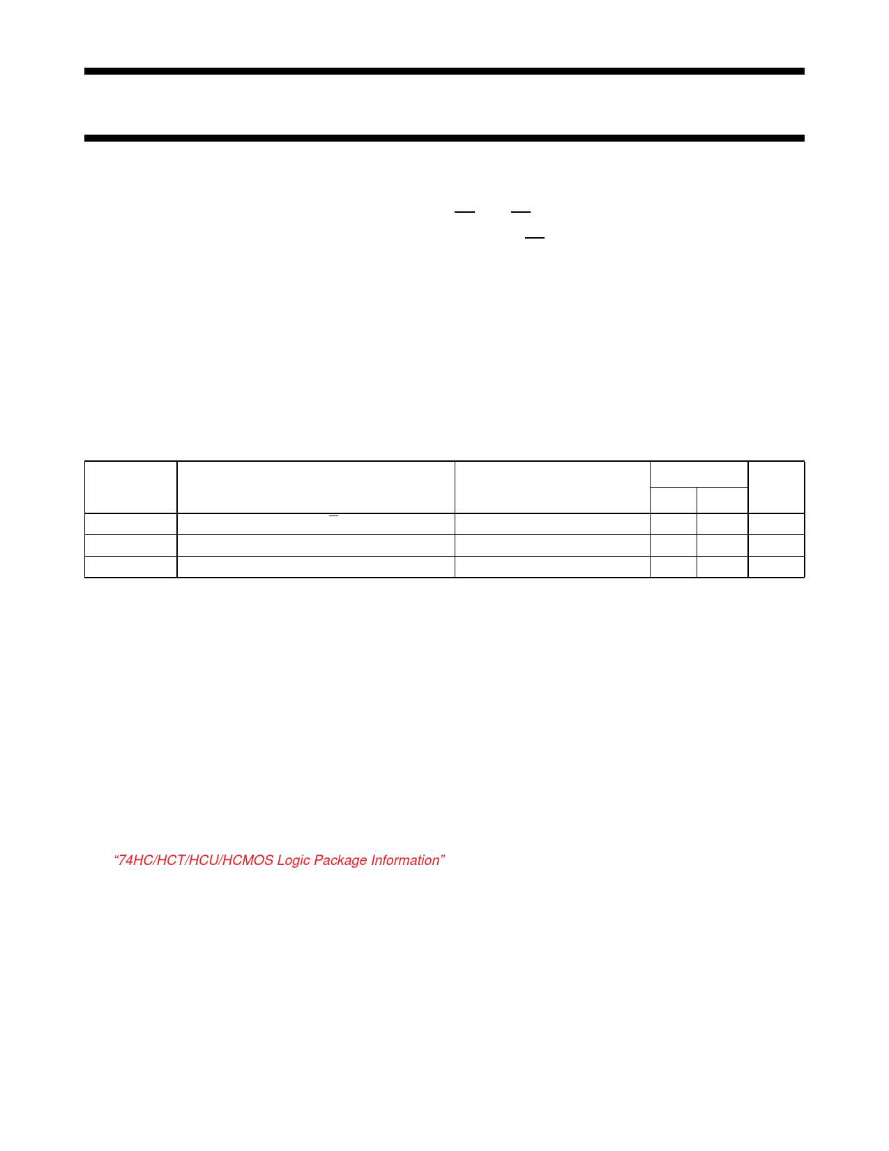
QUICK REFERENCE DATA
GND = 0 V; Tamb = 25 °C; tr = tf = 6 ns
SYMBOL PARAMETER
CONDITIONS
tPHL/ tPLH
CI
CPD
propagation delay An to Yn
input capacitance
power dissipation capacitance per buffer
CL = 15 pF; VCC = 5 V
notes 1 and 2
Notes
1. CPD is used to determine the dynamic power dissipation (PD in µW):
PD = CPD × VCC2 × fi + ∑ (CL × VCC2 × fo) where:
fi = input frequency in MHz
fo = output frequency in MHz
∑ (CL × VCC2 × fo) = sum of outputs
CL = output load capacitance in pF
VCC = supply voltage in V
2. For HC the condition is VI = GND to VCC
For HCT the condition is VI = GND to VCC − 1.5 V
ORDERING INFORMATION
See “74HC/HCT/HCU/HCMOS Logic Package Information”.
TYPICAL
HC HCT
10 16
3.5 3.5
30 32
UNIT
ns
pF
pF
December 1990
2
Share Link: 