WM8181 查看數據表(PDF) - Wolfson Microelectronics plc
零件编号
产品描述 (功能)
生产厂家
WM8181 Datasheet PDF : 14 Pages
| |||
Advanced Information
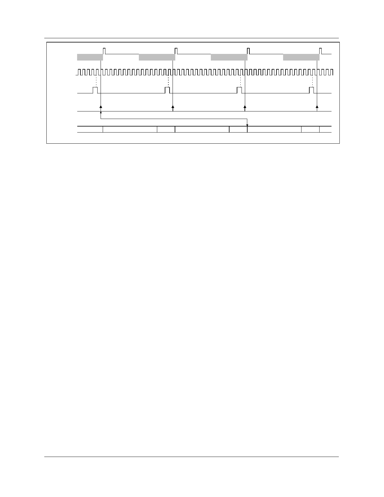
CCD Video Pixel 0
Outputs
MCLK
Reset
Video Pixel 1
Reset
Video Pixel 2
Reset
WM8181
Video Pixel 3
VSMP
S/H
DOUT
LATENCY = 32.5 MCLK PERIODS
D11 → D0 PIXEL - 2 0000 D11 → D0 PIXEL - 1 0000
D11 → D0 PIXEL 0
0000
Figure 5 16:1 Operation
APPLICATIONS RECOMMENDATIONS
INTRODUCTION
The WM8181 is a mixed signal device, therefore careful PCB layout is required. The following
section contains PCB layout guidelines, which are recommended for optimal performance from the
WM8181, and some typical application circuits.
PCB LAYOUT
1) Use separate analogue and digital power and ground planes. The analogue and digital ground
planes should be connected as close as possible to, or underneath, the WM8181.
2) Place all supply decoupling capacitors as close as possible to their respective supply pins and
provide a low impedance path from the capacitors to the appropriate ground.
3) Avoid noise on AGND pins 1 and 2.
4) Avoid noise on reference pins VRT and VRB. Place the decoupling capacitors as close as
possible to these pins and provide a low impedance path from the capacitors to analogue
ground.
5) When VREFIN is used as an external reference control, any noise on VREFIN will degrade the
performance of the ADC. In this case, VREFIN must be carefully de-coupled to AGND.
6) Minimise load capacitance on digital output DOUT. Capacitive loads of greater than 20pF will
degrade performance. Use buffers if necessary and keep tracks short.
TYPICAL APPLICATIONS
The WM8181 is intended for colour scanner applications using a line-by-line architecture and
monochrome scanners, as used in fax machines.
The low pincount and simple digital interface gives the scanner designer the opportunity to place the
ADC near to the sensor. This allows the video information to be converted into the digital domain as
early as possible in the signal chain and minimises analogue noise problems. In the typical
architecture of a flatbed scanner, this means that only power and digital signals appear on the ribbon
minimising crosstalk between the digital clocks and analogue video signals. Care must be taken to
avoid any increase in EMI generated by the higher clock rates on the ribbon cable.
CIS SCANNER
The WM8181 is ideal for use in CIS based scanners where the video output is supplied on a single
output pin. This is true of the majority of colour CIS and all monochrome CIS.
In general, CIS devices provide a video output that becomes more positive for more illumination. This
situation corresponds to the d.c. Coupled Positive Video diagram, Figure 6. The value of the black
reference voltage should be set to be slightly less than the black level output from the CIS to ensure
that the black never saturates.
WOLFSON MICROELECTRONICS LTD
AI Rev 3.0 January 2000
9
Share Link: 