ML4818 查看數據表(PDF) - Fairchild Semiconductor
零件编号
产品描述 (功能)
生产厂家
ML4818 Datasheet PDF : 13 Pages
| |||
ML4818
7
6
5
4
3
SOURCE
2
SINK
1
0
0
0.2
0.4
0.6
0.8
1.0
1.2
1.4
OUTPUT CURRENT (A)
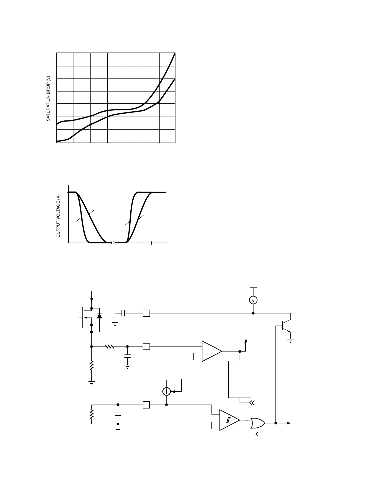
Figure 8. Output Drive Saturation Voltage vs.
Output Current
15
10
5 1nF
10nF
1nF
10nF
PRODUCT SPECIFICATION
Output Driver Stage
The ML4818 has four high current high speed totem pole
output drivers each capable of 1.5A peak output, designed to
quickly switch the gates of capacitive loads, such as power
MOSFET transistors. Figure 8 illustrates the saturation char-
acteristics of the ouput drive transistors shown in Figure 7.
Typical rise and fall time characteristics of the output drivers
are illustrated with capacitive loads of 1nF and 10nF in
Figure 9.
Current Limit, Fault Detection and Soft Start
Current limit is implemented when the current sensed on ILIM
reaches the 1V limit. At this point, the PWM cycle is termi-
nated. The flip flop (Figure 10) turns on the current source to
charge CRST and remains on for the duration of the clock
period. When CRST has charged to 3.4V, a soft start reset
occurs. The number of times the PWM cycle is terminated
due to over-current is “remembered” on CRST. Over time,
CRST is discharged by RRST providing a measure of “forget-
ting” when the over-current condition no longer occurs. This
integrating fault detection is useful in differentiation between
short circuit and load surge conditions.
100 200
tF
(ns)
100 200
tR
Figure 9. Output Rise/Fall Time
ISWITCH
CSS
SOFT START
9
R1
RSENSE
ILIM
4
C1
+
1V
–
V+
V+
I1
TERMINATE
PWM CYCLE
S
Q
RRST
I2
CRST
12
RCRESET
R
CLOCK
+
3.4V
1.3V
–
INHIBIT
OUTPUT
UNDER-VOLTAGE
LOCKOUT
Figure 10. Over-Current, Soft-Start, and Integrating Fault Detect Circuits
8
REV. 1.0.3 6/21/01
Share Link: 