RD5 жҹҘзңӢж•ёж“ҡиЎЁпјҲPDFпјү - Power Integrations, Inc
йӣ¶д»¶зј–еҸ·
дә§е“ҒжҸҸиҝ° (еҠҹиғҪ)
з”ҹдә§еҺӮ家
RD5
Power Integrations, Inc

RD5 Datasheet PDF : 12 Pages
| |||
RD5
General Circuit Description (cont.)
in Figure 12 illustrate the relationship between the high-voltage
DC bus and the 12 V output voltage. Capacitor C1 charges to
the peak of the AC input voltage before TOPSwitch turns on.
The delay of 160 ms (typical) is caused by the time required to
charge the auto-restart capacitor C5 to 5.8 V. At this point the
power supply turns on as shown.
Figure 13 shows the output voltage turn on transient as well as
a family of curves associated with an additional soft-start
capacitor. The soft-start capacitor is placed across VR2 and can
range in value from 4.7 uF to 47 uF as shown.
Line frequency ripple voltage is shown in Figure 14 for 115
VAC input and 20 W output. Switching frequency ripple
voltage is shown in Figure 15 for the same test condition.
The power supply transient response to a step load change from
1.25 to 1.67 A (75% to 100%) is shown in Figure 16. Note that
the response is quick and well damped.
The RD5 is designed to meet worldwide safety and EMI (VDE
B) specifications. Measured conduction emissions are shown
in Figure 17 for 115 VAC and Figure 18 for 230 VAC.
Thermal Considerations
The RD5 utilizes the printed circuit copper for TOPSwitch
heatsinking. For 20 W output, the heatsink area is approximately
1.25 in2 (8 cm2). The copper area required for heatsinking at
15 W output is outlined on the non-component side of the board,
and is approximately 0.56 in2(3.6 cm2). The RD5 printed circuit
board utilizes 2 oz. copper cladding. Printed circuit boards with
lighter cladding will require apertures in the solder mask to
build-up effective trace thickness.
Transformer Specification
The electrical specifications and construction details for
transformer TRD5 are shown in Figures 19 and 20. Transformer
TRD5 is supplied with the RD5 reference design board. This
design utilizes an EI25 core and a triple insulated wire secondary
winding. The use of triple insulated wire allows the transformer
to be constructed using a smaller core and bobbin than a
conventional magnet wire design due to the elimination of the
margins required for safety spacing in a conventional design.
If a conventional margin wound transformer is desired, the
design of Figures 21-22 can be used. This design (TRD5-1)
uses a EEL22 core and bobbin to accommodate the 3 mm
margins required to meet international safety standards when
using magnet wire rather than triple insulated wire, and has the
same pinout and printed circuit foot print as TRD5. The
transformer is approximately 50% taller than the triple insulated
wire design due to the inclusion of creepage margins required
to meet international safety standards.
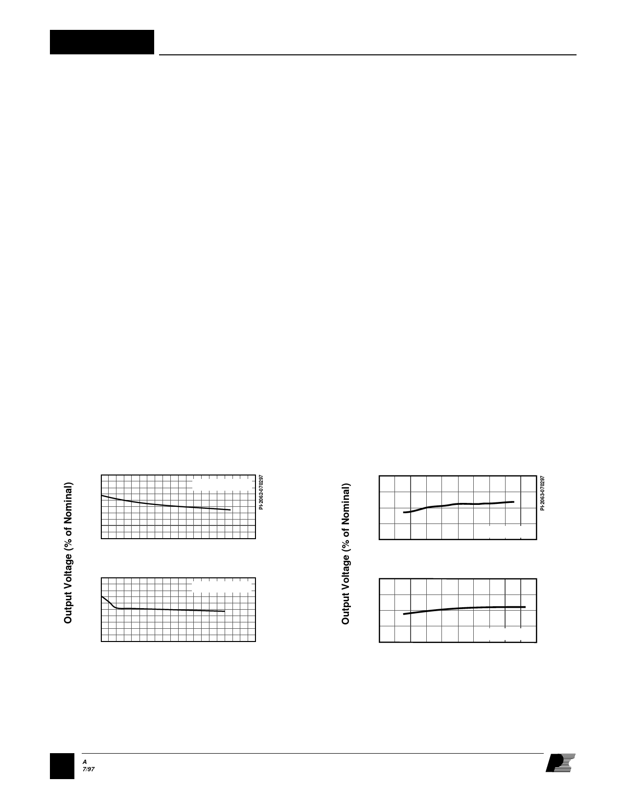
110
VIN = 115 VAC
100
90
0
110
100
0.5
1
1.5
2
Load Current (A)
VIN = 230 VAC
90
0
0.5
1
1.5
2
Load Current (A)
Figure 6. Load Regulation
110
100
90
50
110
IL = 1.67 A
100 150 200 250 300
Input Voltage (VAC)
100
90
50
IL = 0.33 A
100 150 200 250 300
Input Voltage (VAC)
Figure 7. Line Regulation
36 A
7/97
Share Link: