LB11988 查看數據表(PDF) - SANYO -> Panasonic
零件编号
产品描述 (功能)
生产厂家
LB11988 Datasheet PDF : 6 Pages
| |||
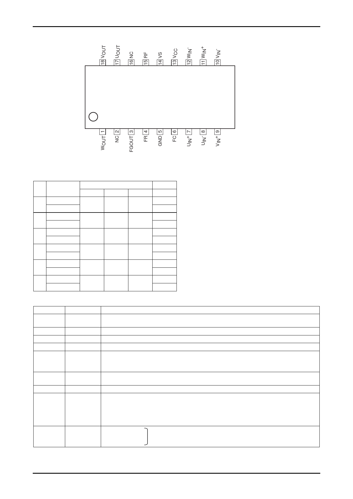
Pin Assignment
LB11988
LB11988
Top view
Truth Table and Control Functions
Source→Sink
V→W
1
W→V
U→W
2
W→U
U→V
3
V→U
W→V
4
V→W
W→U
5
U→W
V→U
6
U→V
Hall input
U
V
W
H
H
L
H
L
L
H
L
H
L
L
H
L
H
H
L
H
L
Note : The “H” state for FR is defined as a voltage of 8V or higher, and the
W
“L” state for FR is defined as a voltage of 4V or lower.
H
(When VCC = 12V.)
L
Note : For the Hall inputs, the input high state is defined to be the state
H
where the (+) input is higher than the corresponding (-) input by
L
0.01V or higher, and the input low state is defined to be the state
H
where the (+) input is lower than the corresponding (-) input by
L
0.01V or higher.
H
L
H
L
Note : Since this drive technique is a 180° current application scheme, the
H
phases other than the sink and the source phases will not turn off.
L
Pin Functions
Pin No.
Pin name
5
GND
3
4
6
7, 8
9, 10
11, 12
13
14
15
FGOUT
FR
FC
UIN+, UIN-
VIN+, VIN-
WIN+, WIN-
VCC
VS
Rf
17
UOUT
18
VOUT
1
WOUT
Function
Ground for circuits other than the output transistors.
Note that the Rf pin will be at the lowest potential of the output transistors.
This is the FG amplifier output pin. Internally, it is a resistive load. (Pull up)
Forward/reverse switching pin
Corrects the frequency characteristics of the saturation prevention circuit loop and current limiter circuit.
U-phase Hall input. Logic high refers to the state where IN+ > IN-.
V-phase Hall input. Logic high refers to the state where IN+ > IN-.
W-phase Hall input. Logic high refers to the state where IN+ > IN-.
Power supply provided to all IC internal circuits other than the output block.
This voltage must be stabilized so that ripple and noise do not enter the IC.
Output block power supply
Used for output current detection. The current limiter circuit operates using the resistor (Rf) connected between this
pin and ground.
Note that the lower side saturation prevention circuit operates according to the voltage that appears on this pin.
Since the over-saturation level is set by this voltage, the level of the lower side saturation prevention circuit may be
degraded in the large current region if the value of Rf is made extremely small.
U-phase Hall output.
V-phase Hall output. (These pins include internal spark killer diodes.)
W-phase Hall output.
No.6211-3/6
Share Link: 