PCF8575CTS/F1 查看數據表(PDF) - Philips Electronics
零件编号
产品描述 (功能)
生产厂家
PCF8575CTS/F1 Datasheet PDF : 24 Pages
| |||
Philips Semiconductors
Remote 16-bit I/O expander for I2C-bus
Product specification
PCF8575C
6 FUNCTIONAL DESCRIPTION
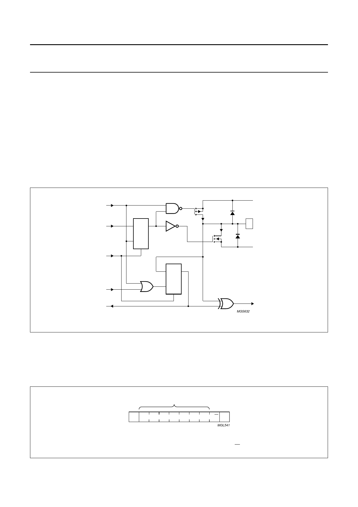
6.1 Quasi-bidirectional I/Os
The 16 ports (see Fig.3) are entirely independent and can be used either as input or output ports. Input data is transferred
from the ports to the microcontroller in the READ mode (see Fig.6). Output data is transmitted to the ports in the WRITE
mode (see Fig.5).
This quasi-bidirectional I/O can be used as an input or output without the use of a control signal for data direction.
At power-on all the I/Os are in 3-state mode. The strong pull-up to VDD (IOHt) allows a fast rising edge into a heavily
loaded output. This strong pull-up turns on when the output is written HIGH, and is switched off by the negative edge of
SCL. After this short period the output is in 3-state mode. The I/O should be written HIGH before being used as an input.
After power-on as all the I/Os are set to 3-state all of them can be used as inputs. Any change in setting of the I/Os as
either inputs or outputs can be done with the write mode. Warning: If a HIGH is applied to an I/O which has been written
earlier to LOW, a large current (IOL) will flow to VSS (see Chapter 10; note 3).
handbook, full pagewidth
write pulse
data from
shift register
power-on
reset
read pulse
data to
shift register
DQ
FF
CI
S
VDD
IOHt
P00 to P07
IOL
P10 to 17
VSS
DQ
FF
CI
S
MGS632
to interrupt
logic
Fig.3 Simplified schematic diagram of each I/O.
6.2 Addressing
Figures 4, 5 and 6 show the address and timing diagrams. Before any data is transmitted or received the master must
send the address of the receiver via the SDA line. The first byte transmitted after the START condition carries the address
of the slave device and the read/write bit. The address of the slave device must not be changed between the START and
the STOP conditions. The PCF8575C acts as a slave receiver or a slave transmitter.
1999 Aug 05
handbook, halfpage
slave address
S 0 1 0 0 A2 A1 A0 R/W A
MGL541
Fig.4 Byte containing the slave address and the R/W bits.
6
Share Link: 