STV3012 查看數據表(PDF) - STMicroelectronics
零件编号
产品描述 (功能)
生产厂家
STV3012 Datasheet PDF : 8 Pages
| |||
STV3012
I.4 - Oscillator Input and Output
The external components must be connected to
these pins when using an oscillator with a ceramic
resonator. The oscillator frequency may vary be-
tween 350kHz and 600kHz as defined by the reso-
nator. No external feedback resistor is allowed.
II - FUNCTIONAL DESCRIPTION
Key operation (see Figure 3) :
In the stand-by mode all drivers (DRV0N to
DRV6N) are on (low impedance to VSS). Whenever
a key is pressed, one or more of the sense inputs
(SENnN) are tied to ground. This will start the
power-up sequence. First the oscillator is activated
and after the debounce time tDB the output drivers
(DRV0N to DRV6N) become active successively.
Within the first scan cycle, the transmission mode,
the applied sub-system address and the selected
command code are sensed and loaded into an
internal data latch.
In contrast to the command code, the sub-system
is sensed only within the first scan cycle. If the
applied sub-system address is changed while the
Command key is pressed, the transmitted sub-sys-
tem address is not altered.
In a multiple key stroke sequence the command
code is always altered in accordance with the
sensed key.
III - OUTPUT SEQUENCE (DATA FORMAT)
The output operation will start when the selected
code is found. A burst of pulses, including the
latched address and command codes, is generated
at the output REMO as long as a key is pressed.
The operation is terminated by releasing the key or
if more than one key is pressed at the same time.
Once a sequence is started, the transmitted data
words will always be completed after the key is
released.
The toggle bits T1 and T0, during mode A only T0,
toggle if the key is released for a minimum time
tREL. The toggle bits remain unchanged within a
multiple key-stroke sequence.
IV - MULTIPLE KEY-STROKE PROTECTION
The keyboard is protected against multiple key-
strokes (Figure 4). If more than one key is pressed
at the same time, the circuit will not generate a new
output at REMO. In case of a multiple key-stroke,
the scan repetition rate is increased to detect the
release of a key as soon as possible.
There are two restrictions caused by the special
structure of the keyboard matrix : the keys switch-
ing to ground (code numbers 7, 15, 23, 31, 39, 47,
55 and 63) and the keys connected to SEN5N and
SEN6N are not covered completely by the multiple
key protection. If one sense input is switched to
ground, further keys on the same sense line are
ignored, i.e. the command code corresponding to
"key to ground" is transmitted. SEN5N and SEN6N
are not protected against multiple keystroke on the
same driver line, because this condition has been
used for the definition of additional codes (code
number 56 to 63).
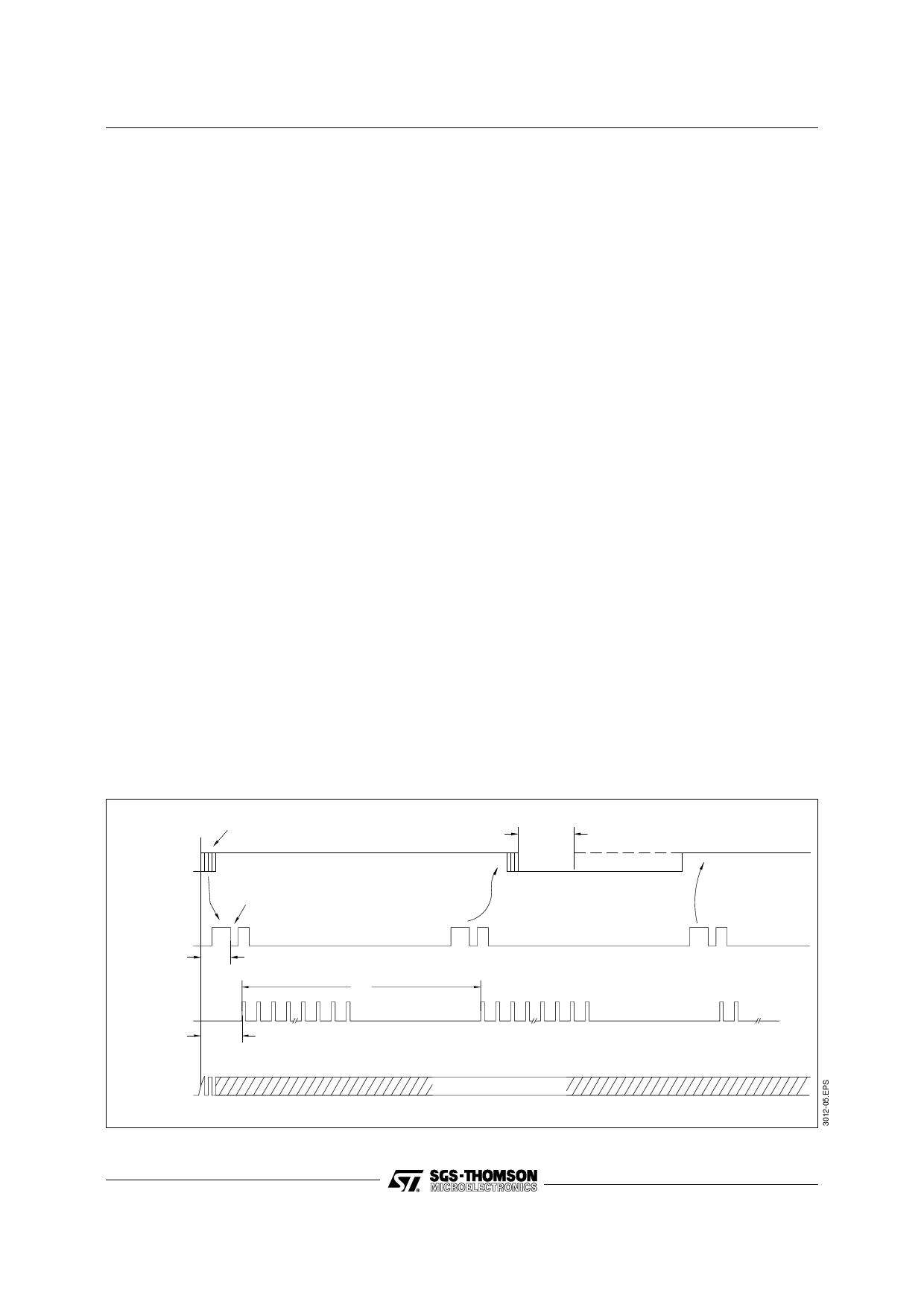
Figure 3 : Single Key-stroke Sequence. Debounce time : tDB = 4 to 9 x t0,
Start time : tST = 5 to 10 x t0, Minimum release time : tREL = t0.
REV closed
released
key bouncing
scan
DRVnN off
on
t DB
H
REMO
L
tW
t ST
scan
t REL
new key
scan
new word
H
OSCO
L
OSCILLATOR ACTIVE
6/8
Share Link: 