STK6877 查看數據表(PDF) - SANYO -> Panasonic
零件编号
产品描述 (功能)
生产厂家
STK6877 Datasheet PDF : 8 Pages
| |||
STK6877
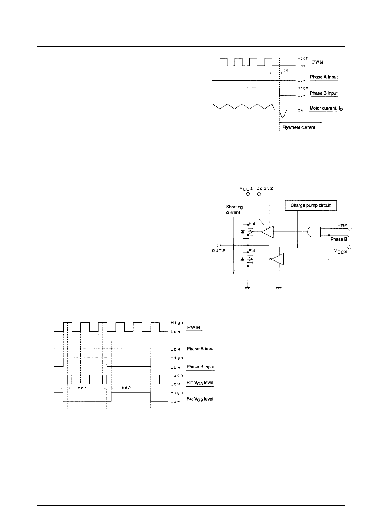
The dead time (td) and the flywheel current must be checked
with the motor actually used, since the amount of dead time (td)
that must be inserted between setting the PWM input low and
setting the A and B phase inputs low to assure that the flywheel
current is held within the maximum rated range will vary with
the conditions under which the circuit operates. (See Figure 12.)
Method (c) allows the motor to be stopped in a much shorter
time than is possible with method (b). When releasing the brake
it does not matter if the phase input signals or the PWM input
signal is set high first.
Although we have presented three braking methods, we
recommend the use of method (c) due to the speed of braking
and the current levels flowing during the braking operation.
Note: (*) Braking applied during reverse motor rotation
Figure 12 Input Signal Timing Chart for
Braking Method (c)
5. Upper and Lower MOSFET Shorting Currents
It is conceivable that both the upper and lower MOSFETs could
be in the on state at the same time during braking operations
(braking methods (a) and (c)) and release states. Taking this into
consideration, the STK6877 provides two dead times (td1 and
td2) of at least 1 µs with respect to the input signals in the upper
and lower MOSFET drive circuits as shown in the figure below.
As a result there is no need for concern about shorting currents in
the upper and lower MOSFETs.
Figure 13 Upper and Lower MOSFET
Equivalent Circuit
Note: td1: Dead time in the upper MOSFET drive circuit
td2: Dead time in the lower MOSFET drive circuit
(*) td1, td2 ≥ 1 µs
Figure 14 Upper and Lower MOSFET VGS Voltage Timing Chart
No. 4874-7/8
Share Link: 