ICS9110-01CS14 查看數據表(PDF) - Integrated Circuit Systems
零件编号
产品描述 (功能)
生产厂家
ICS9110-01CS14 Datasheet PDF : 10 Pages
| |||
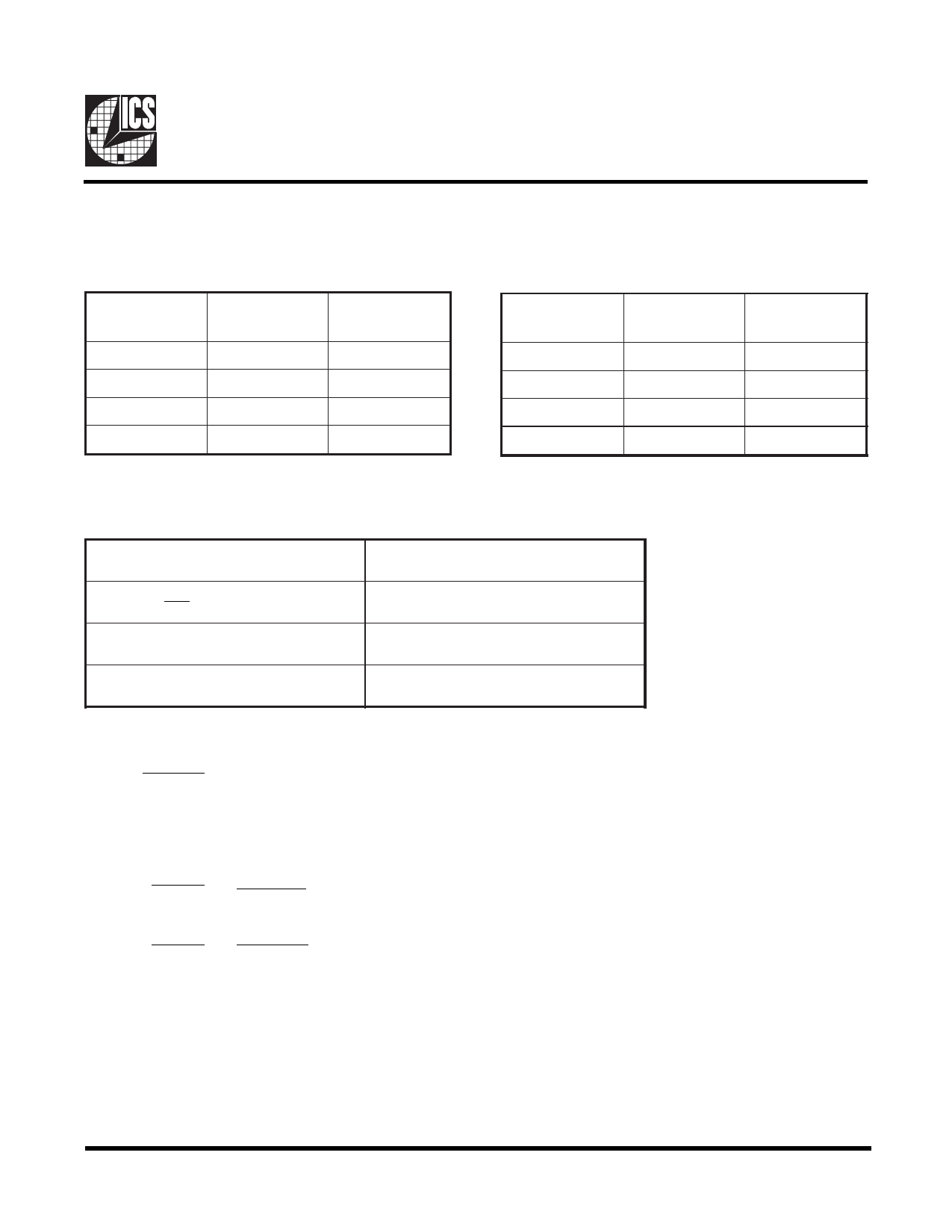
AV9110
Output Divider Turth Tables
COD1
0
0
1
1
Table 2
COD0
0
1
0
1
CLK/X
Output Divide
(X)
1
2
4
8
COD1
0
0
1
1
Table 3
COD0
0
1
0
1
VCO
Output Divide
(R)
1
2
4
8
Programming the PLL
The AV9110 has a wide operating range but it is recommended that it is operated within the following limits:
2 MHz < fREF < 32 MHz
fREF
200 kHz <
< 5MHz
M
50 MHz < f <250 MHz
VCO
fREF = Input reference frequency
M = Reference divide, 3 to 127
f = VCO output frequency
VCO
fVCO < 250 MHz
fCLK = CLK or CLK/X output frequency
The AV9110 is a classical PLL circuit and the VCO output frequency is given by:
fVCO =
N•V• fREF
Where
N = VCO divided, 3 to 127
M
M =m Reference divide, 3 to 127
V = Perscale, 1 or 8
The 2 output drivers then give the following frequencies:
fCLK =
fVCO = N•V• fREF or fREF (output mixable by bit 17)
R
MR
fCLK/X =
fVCO =
R•X
fVCLK
X
Where R, X = output dividers 1, 2, 4 or 8
Notes:
1. Output frequency accuracy will depend solely on input reference frequency accuracy.
2. For output frequencies below 125 MHz, it is recommended that the VCO output divide, R, should be 2 or greater. This will
give improved duty cycle.
3. The minimum output frequency step size is approximately 0.2% due to the divider range provided.
5
Share Link: 