NTE266 查看數據表(PDF) - NTE Electronics
零件编号
产品描述 (功能)
生产厂家
NTE266 Datasheet PDF : 2 Pages
| |||
Electrical Characteristics: (TA = +25°C unless otherwise specified)
Parameter
Symbol
Test Conditions
Min Typ Max Unit
Forward Current Transfer Ratio
Collector Saturation Voltage
Base Saturation Voltage
Collector Cutoff Current
Emitter Cutoff Current
Input Impedance
Collector Capacitance
Gain Bandwidth Product
Delay Time and Rise Time
Storage Time
Fall Time
hFE IC = 200mA, VCE = 5V
40k – –
hfe IC = 20mA, VCE = 5V, f = 1kHz – 20k –
VCE(sat) IC = 500mA, IB = 0.5mA, Note 2 –
– 1.5 V
VBE(sat) IC = 500mA, IB = 0.5mA, Note 2 –
– 2.0 V
ICES VCE = 50V, TJ = +25°C
– – 0.5 µA
ICBO VCE = 50V, TJ = +150°C
– – 20 µA
IEBO VEB = 13V
– – 0.1 µA
hie IC = 20mA, VCE = 5V, f = 1kHz 50 500 – Ω
Ccbo VCB = 10V, f = 1MHz
– 5 10 pF
fT VCE = 5V, IC = 20mA
– 75 – MHz
td + tr IC = 1A, IB1 = 1mA
– 100 – ns
ts IC = 1A, IB1 = IB2 = 1mA
– 350 – ns
tf IC = 1A, IB1 = IB2 = 1mA
– 800 – ns
Note 2. Pulsed measurement: Pulse Width = 300µs, Duty Cycle ≤ 2%.
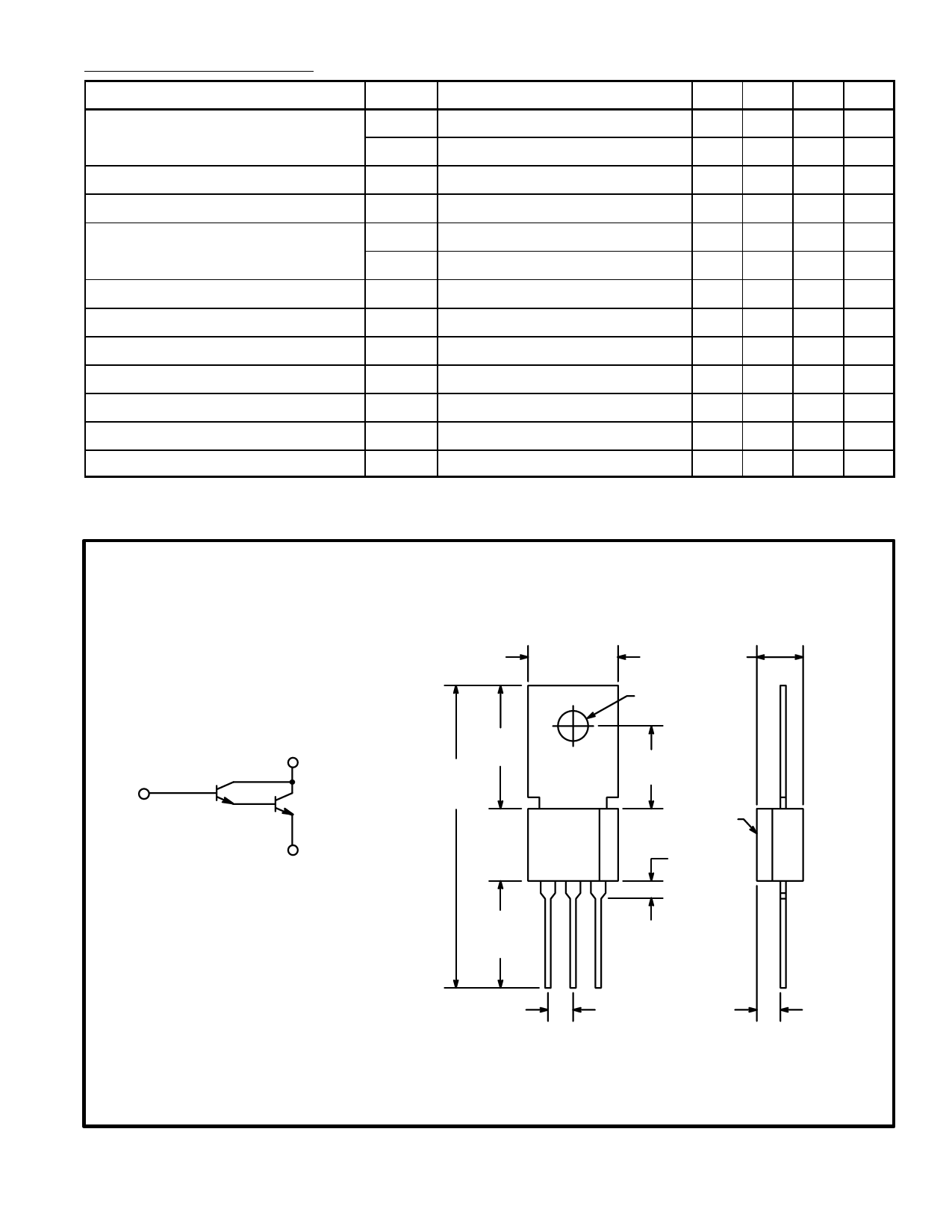
.380 (9.56)
.180 (4.57)
C
.132 (3.35) Dia
.500
C
(12.7)
1.200
.325
(9.52)
B
(30.48)
Ref
.070 (1.78) x 45°
.300
Chamf
E
(7.62)
.050 (1.27)
.400
(10.16)
Min
E BC
.100 (2.54)
.100 (2.54)
Share Link: 