ST3917B 查看數據表(PDF) - STMicroelectronics
零件编号
产品描述 (功能)
生产厂家
ST3917B Datasheet PDF : 16 Pages
| |||
ST3917A - ST3917B
PIN DESCRIPTION (continued)
SEL (Input, Pin 4)
This is an option selectable pin for four Flash
duration. The four options are summarised in the
table 2.
For option 1, softswitch feature is inhibited. It
means redialed by the LND key in pulse mode will
not repeat the softswitch and subsequent digits,
only pulse digits are dialed out.
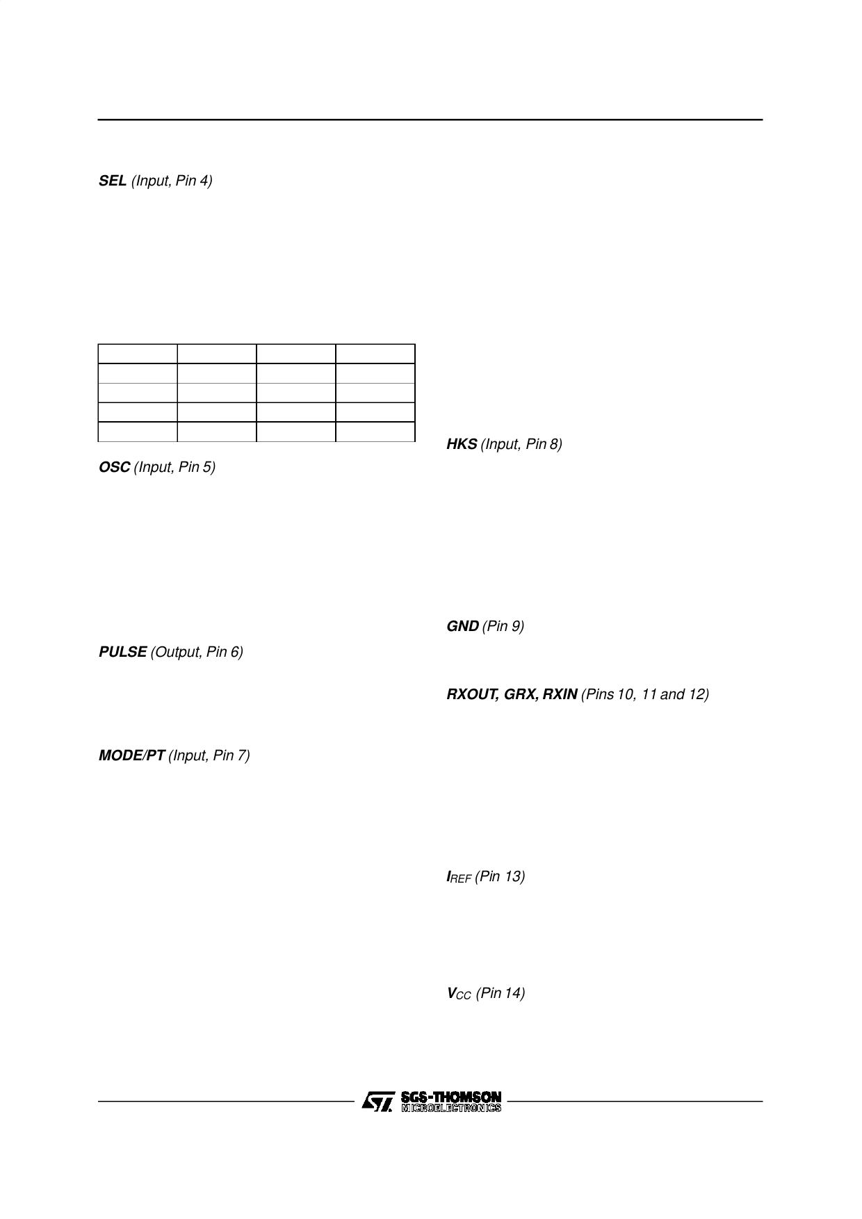
Table 2 : Options Selectable for Flash Duration
Options
1
2
3
4
SEL
VDD
GND
Any Row
Any Col
Flash (ms)
100
600
300
100
Softswitch
Inhibited
Enable
Enable
Enable
OSC (Input, Pin 5)
Only one pin is needed to connect the ceramic
resonator to the oscillator circuit. The other end of
the resonator is connected to GND. The nominal
resonator frequency is 3.579545MHz and any de-
viation from this standard is directly reflected in the
Tone output frequencies. The ceramic resonator
provides the time reference for all circuit functions.
A ceramic resonator with tolerance of ±0.25% is
recommended.
PULSE (Output, Pin 6)
This is an output consisting of an open drain N-
channel device. During on-hook, pulse output pin
is in high impedance and once off-hook, it will be
pulled high by external resistor.
MODE/PT (Input, Pin 7)
Input (MODE). MODE determines the dialer’s de-
fault operating mode. When the device is powered
up or the hookswitch input is switched from on-
hook (VDD) to off-hook (GND), the default deter-
mines the signalling mode. A VDD connection
defaults to tone mode operation and a GND con-
nection defaults to pulse mode operation.
When dialing in the pulse mode, a softswitch fea-
ture will allow a change to the tone mode whenever
the * or softswitch key (TONE) is depressed. Sub-
sequent * key inputs will cause the DTMF code for
an * to be dialed. The softswitch will only switch
from pulse to tone. The phone will be in pulse mode
only after returning to on-hook and back to off-
hook. Redialed by the LND key will repeat the
softswitch unless the softswitch redial feature is
inhibited.
Output (PT). Pacifier Tone Output. In pulse mode,
all valid key entries activate the pacifier tone. In
tone mode, any non DTMF entry (FLASH, PAUSE,
LND, TONE) activates the pacifier tone. The paci-
fier tone provides audible feedback, confirmingthat
the key has been properly entered and accepted.
It is a 500Hz square wave activated upon accep-
tance of valid key input after the 32ms debounce
time.
The square wave terminates after 75ms typically or
when the valid key is no longer present. The pacifier
tone signal is simultaneously sent to the earphone
and the buzzer. The buzzer can be removed with-
out affecting this function. The resistor value set on
MODE/PT pin determines the level of the pacifier
tone in the earphone.
HKS (Input, Pin 8)
This is the hookswitch input to the device. It is a
CMOS input with a high pull up internal resistance
and must be switched high or open for on-hook
operation and low for off-hook operation. A transi-
tion on this input causes the on-chip logic to initial-
ize, terminating any operation in progress at the
time. The signalling mode defaults to the mode
selected at MODE/PT pin. Figures 2, 3 and 4, 5
illustrate the timing for this pin.
GND (Pin 9)
GND is the negative line terminal of the device.This
is the voltage reference for all specifications.
RXOUT, GRX, RXIN (Pins 10, 11 and 12)
The receive amplifier has one input RXIN and a non
inverting output RXOUT. Amplification from RXIN
to RXOUT is typically 31dB and it can be adjusted
between 21dB and 41dB to suit the sensitivity of
the earphone used. The amplification is propor-
tional to the external resistor connected between
GRX and RXOUT. For the hearing impaired, a
specific application to offer 17dB additional gain at
3kHz is permitted.
IREF (Pin 13)
An external resistor of 3.6kΩ connected between
IREF and GND will set the internal current level.
Any change of this resistor value will influence the
microphone gain, DTMF gain, earphone gain and
sidetone level.
VCC (Pin 14)
VCC is the positive supply of the speech network. It
can be stabilized by a decoupling capacitor be-
tween VCC and GND. The VCC supply voltage may
also be used to supply external peripheral circuits.
3/16
Share Link: 