L9935013TR 查看數據表(PDF) - STMicroelectronics
零件编号
产品描述 (功能)
生产厂家
L9935013TR Datasheet PDF : 29 Pages
| |||
L9935
4
Application hints
Application hints
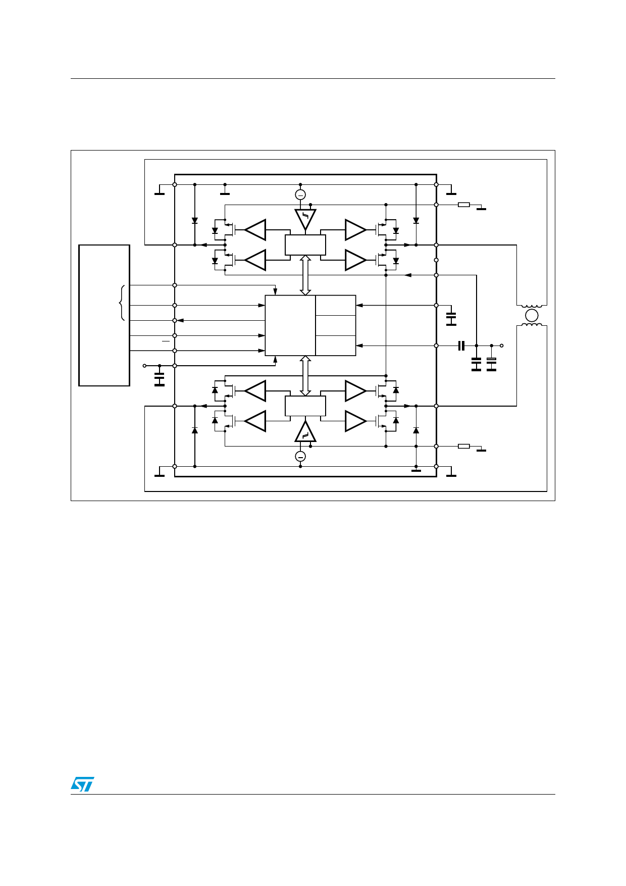
Figure 3. General application circuit proposal
'.$
/54!
3$)
).4%2&!#%
M#
3#+
3$)
3$/
#3.
%.
6 6##
N&
/54"
^
$2)6%2
,/')#
#/--/.
,/')#
/3#),,!4/2
$)!'./34)#
")!3).'
$2)6%2
,/')#
'.$
32!
2�7
/54!
.#
63
/3#
#/3#
N&
#$RIVER
N&
#$26
#
N&
34%00%2
-/4/2
0/7%2
3500,9
#
M&
/54"
^
'.$
32"
2�7
'.$
'!0'03
C1 and C2 should be placed as close to the device as possible. Low ESR of C2 is
advantageous. Peak currents through C1 and C2 may reach 2 A. Care should be taken that
the resonance of C1, C2 together with supply wire inductances is not the chopping
frequency or a multiple of it.
Doc ID 5198 Rev 10
11/29
Share Link: 