AD743AN 查看數據表(PDF) - Analog Devices
零件编号
产品描述 (功能)
生产厂家
AD743AN Datasheet PDF : 12 Pages
| |||
AD743
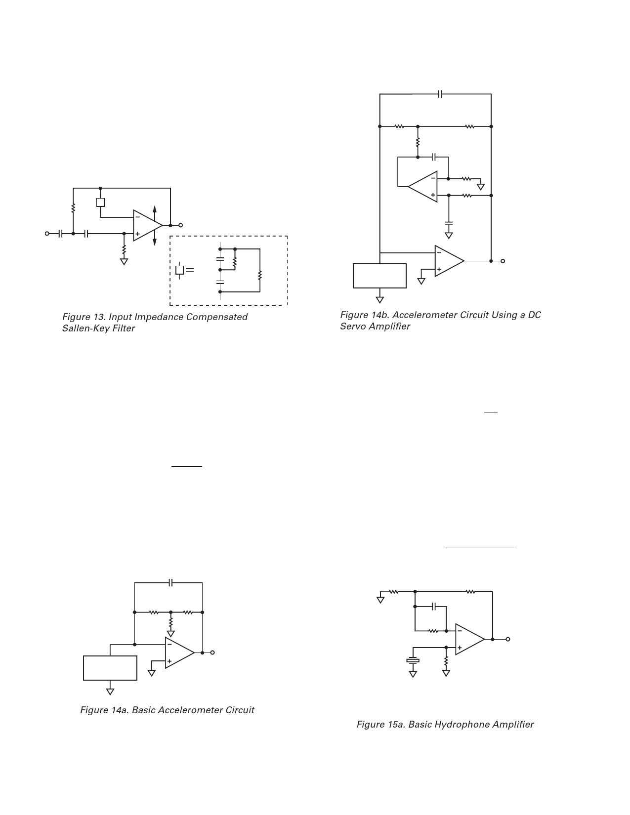
AN INPUT IMPEDANCE COMPENSATED, SALLEN-KEY
FILTER
The simple high-pass filter of Figure 13 has an important source
of error which is often overlooked. Even 5 pF of input capacitance
in amplifier A will contribute an additional 1% of pass-band ampli-
tude error, as well as distortion, proportional to the C/V characteristics
of the input junction capacitance. The addition of the network
designated Z will balance the source impedance—as seen by
A—and thus eliminate these errors.
Z
500k⍀
1000pF 1000pF
500k⍀
+VS
A
–VS
1000pF
Z
1000pF
500k⍀
500k⍀
C1
1250pF
R1
110M⍀
(5 ؋ 22M⍀)
R2
9k⍀
R3
1k⍀
C2
2.2F
AD711
R4
18M⍀
R5
18M⍀
C3
2.2F
B AND K MODEL
4370 OR
EQUIVALENT
AD743
OUTPUT
0.8mV/pC
Figure 13. Input Impedance Compensated
Sallen-Key Filter
TWO HIGH PERFORMANCE ACCELEROMETER
AMPLIFIERS
Two of the most popular charge-out transducers are hydrophones
and accelerometers. Precision accelerometers are typically cali-
brated for a charge output (pC/g).* Figures 14a and 14b show
two ways in which to configure the AD743 as a low noise charge
amplifier for use with a wide variety of piezoelectric accelerom-
eters. The input sensitivity of these circuits will be determined
by the value of capacitor C1 and is equal to
∆VOUT
=
∆QOUT
C1
The ratio of capacitor C1 to the internal capacitance (CT) of the
transducer determines the noise gain of this circuit (1 + CT/C1).
The amplifier’s voltage noise will appear at its output amplified
by this amount. The low frequency bandwidth of these circuits
will be dependent on the value of resistor R1. If a T network is
used, the effective value is R1(1 + R2/R3).
C1
1250pF
R1
110M⍀
(5 ؋ 22M⍀)
R2
9k⍀
R3
1k⍀
B AND K MODEL
4370 OR
EQUIVALENT
AD743
OUTPUT
0.8mV/pC*
*pC = PICOCOULOMBS
g = EARTH’S GRAVITATIONAL CONSTANT
Figure 14a. Basic Accelerometer Circuit
Figure 14b. Accelerometer Circuit Using a DC
Servo Amplifier
A dc servo loop (Figure 14b) can be used to assure a dc output
which is <10 mV, without the need for a large compensating
resistor when dealing with bias currents as large as 100 nA. For
optimal low frequency performance, the time constant of the
servo loop (R4C2 = R5C3) should be
Time Constant ≥ 10 R11 + RR23C1
LOW NOISE HYDROPHONE AMPLIFIER
Hydrophones are usually calibrated in the voltage out mode.
The circuits of Figures 15a and 15b can be used to amplify the
output of a typical hydrophone. Figure 15a shows a typical
dc-coupled circuit. The optional resistor and capacitor serve
to counteract the dc offset caused by bias currents flowing through
resistor R1. Figure 15b, a variation of the original circuit, has a
low frequency cutoff determined by an RC time constant equal to
Time Constant =
1
2 π × CC × 100 Ω
R3
100⍀
R2
1900⍀
C1*
B AND K TYPE 8100
HYDROPHONE
CT
R4*
108⍀
R1
108⍀
AD743
OUTPUT
INPUT SENSITIVITY = –179 dB re. 1V/Pa**
*OPTIONAL, SEE TEXT
**1V PER MICROPASCAL
Figure 15a. Basic Hydrophone Amplifier
–10–
REV. E
Share Link: 