AD698 查看數據表(PDF) - Analog Devices
零件编号
产品描述 (功能)
生产厂家
AD698 Datasheet PDF : 12 Pages
| |||
10
0
0.033µF
–10
–20
0.1µF
0.01µF
–30
–40
–50
–60
R2 = 81kΩ
fEXC = 10kHz
–70
0
0.033µF
–60
–120
–180
–240
–300
–360
R2 = 81kΩ
fEXC = 10kHz
0.1µF
0.01µF
–420
0
100
1k
10k
FREQUENCY – Hz
100k
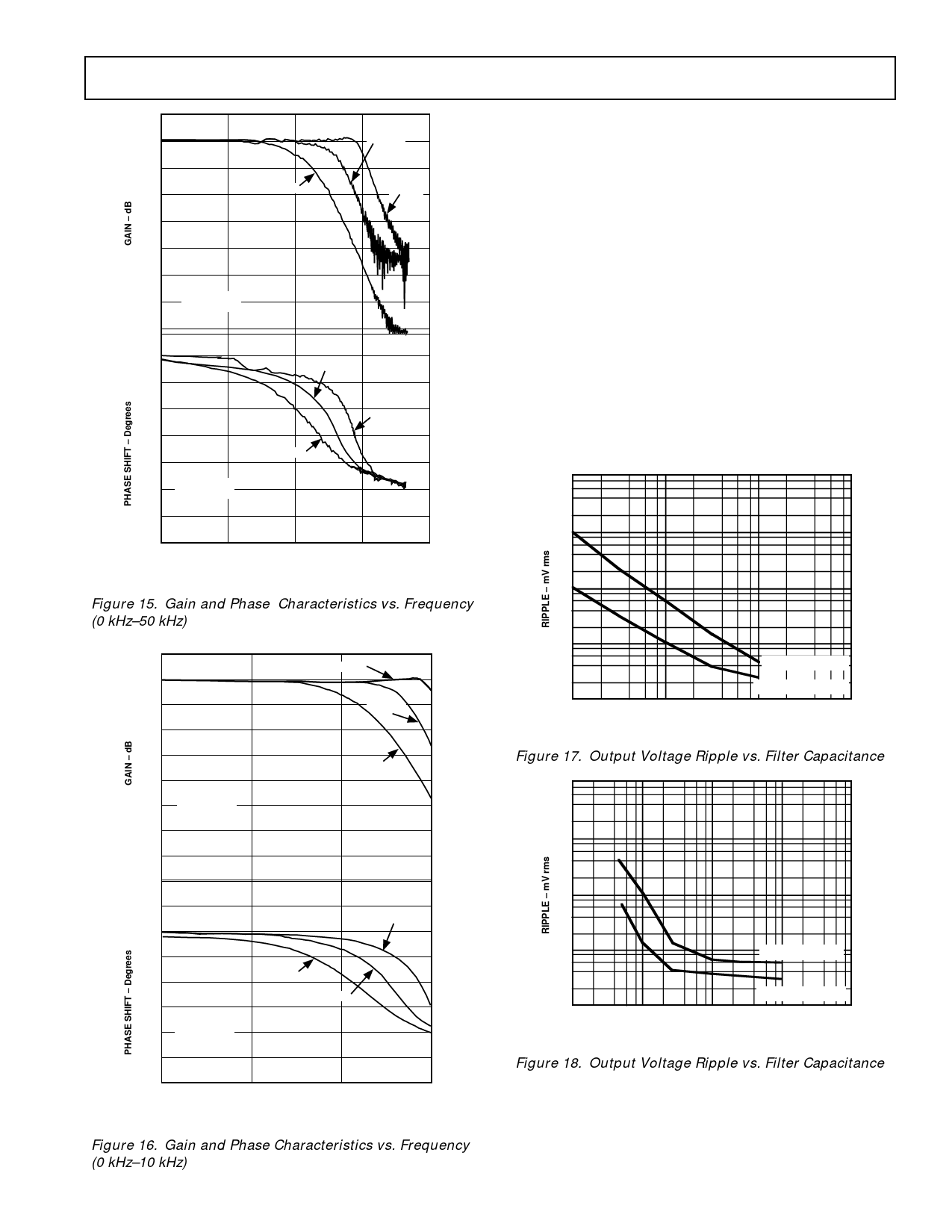
Figure 15. Gain and Phase Characteristics vs. Frequency
(0 kHz–50 kHz)
10
0
–10
–20
–30
–40
–50
R2 = 81kΩ
fEXC = 10kHz
–60
–70
0.01µF
0.033µF
0.1µF
AD698
Figure 16 shows a more limited frequency range with enhanced
accuracy. The figures are transfer functions with the input to be
considered as a sinusoidally varying mechanical position and the
output as the voltage from the AD698; the units of the transfer
function are volts per inch. The value of C2, C3, and C4, from
Figure 7, are all equal and designated as a parameter in the fig-
ures. The response is approximately that of two real poles.
However, there is appreciable excess phase at higher frequen-
cies. An additional pole of filtering can be introduced with a
shunt capacitor across R2, Figure 7; this will also increase phase
lag.
When selecting values of C2, C3 and C4 to set the bandwidth of
the system, a trade-off is involved. There is ripple on the “dc”
position output voltage, and the magnitude is determined by the
filter capacitors. Generally, smaller capacitors will give higher
system bandwidth and larger ripple. Figures 17 and 18 show the
magnitude of ripple as a function of C2, C3 and C4, again all
equal in value. Note also a shunt capacitor across R2, Figure 7,
is shown as a parameter. The value of R2 used was 81 kΩ with a
Schaevitz E100 LVDT.
1k
100
10
1
0.1
0.01
2.5kHz, CSHUNT 1nF
2.5kHz, CSHUNT 10nF
0.1
1
10
C2, C3, C4; C2 = C3 = C4 – µF
Figure 17. Output Voltage Ripple vs. Filter Capacitance
1k
100
0
–60
–120
–180
–240
–300
R2 = 81kΩ
fEXC = 10kHz
0.1µF
0.033µF
–360
0
100
1k
FREQUENCY – Hz
0.01µF
10k
10
1
10kHz, CSHUNT 1nF
0.1
0.001
10kHz, CSHUNT 10nF
0.01
0.1
1
10
C2, C3, C4; C2 = C3 = C4 – µF
Figure 18. Output Voltage Ripple vs. Filter Capacitance
Figure 16. Gain and Phase Characteristics vs. Frequency
(0 kHz–10 kHz)
REV. B
–9–
Share Link: 