ZXBM2001 查看數據表(PDF) - Zetex => Diodes
零件编号
产品描述 (功能)
生产厂家
ZXBM2001 Datasheet PDF : 10 Pages
| |||
ZXBM2001
ZXBM2002 ZXBM2003
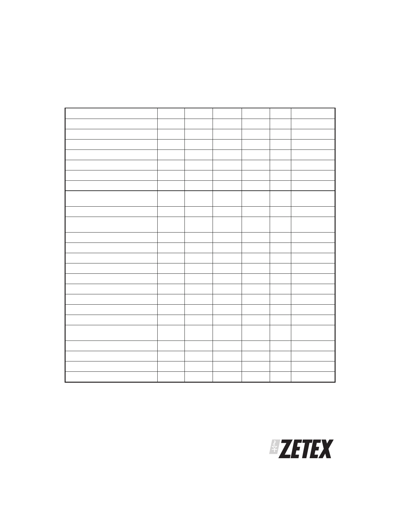
Electrical Characteristics (at Tamb = 25°C & VCC = 12V)
Parameter
Symbol
Min
Typ
Supply Voltage
Supply Current
Hall Amp Input Voltage
VCC
4.5
ICC
2.2
40
Hall Amp Common Mode Voltage
Hall Amp Input Offset
Hall Amp Bias Current
PH1, PH2 Output High
PH1, PH2 Output Off Leakage
Current
VCM
VOFS
VBS
VOH
IOFF
0.5
VCC-2.2
0.5VCC
±7
-350
VCC-1.8
PH1, PH2 Output Current High
Lock/FG Maximum Collector
Voltage
IOH
VOH
Lock/FG Sink Current
Lock/FG Low Level O/P Voltage
CLCK Charge Current
CLCK Discharge Current
Lock condition On:Off ratio
IOL
VOL
ILCKC
ILCKD
-1.8
1:7
0.3
-2.8
0.28
1:10
CLCK High Threshold Voltage
CLCK Low Threshold Voltage
CPWM Charge Current
CPWM Discharge Current
PWM Frequency
VTHH
2.0
VTHL
1.0
IPWMC
3.6
4.3
IPWMD
50
62
FPWM
24
34
CPWM High Threshold Voltage
VTHH
2.0
CPWM Low Threshold Voltage
VTHL
1.0
SPD Voltage Control Range
VSPD
1
SPD Open Circuit Voltage
1.5
Max
18
3.25
VCC-1.5
Ϯ10
-80
VCC
5
0.5
0.35
5.0
75
2
Unit
V
mA
mV
V
mV
nA
V
A
mA
V
mA
V
A
A
V
V
A
A
kHz
kHz
V
V
V
V
Conditions
No Load 1
diff p-p
IOH = 80mA
IOL = 5mA
Vin = 1.5V
Vin = 1.5V
Vin = 1.5V
Vin = 1.5V
CPWM = 150pF
CPWM = 100pF
2
3
Notes:
1 Measured with pins H+, H-, CLCK and CPWM = 0V and all other signal pins open circuit.
2 The 1V minimum represents 100% PWM drive and 2V represents 0% PWM drive.
3 This voltage is determined by an internal resistor network of 52.5k⍀ from the pin to Gnd and 19.5k⍀ from the pin to a 2V reference. Whilst both
resistors track each other the absolute values are subject to a ±20% manufacturing tolerance
ISSUE 4 - OCTOBER 2004
3
SEMICONDUCTORS
Share Link: 