M52775 查看數據表(PDF) - MITSUBISHI ELECTRIC
零件编号
产品描述 (功能)
生产厂家
M52775 Datasheet PDF : 34 Pages
| |||
MITSUBISHI ICs (TV)
M52775FP
VIF, SIF, VIDEO, CHROMA, DEFLECTION FOR NTSC
ELECTRICAL CHARACTERISTICS TEST METHOD
P/N Video S/N
1. Input SG3 and measure the rms value of output signal at pin 57.
2. P/N is defined as follows:
P/N=20log V0NEG measured value (VP-P) ×103×0.7
Measured value (mVrms)
(dB)
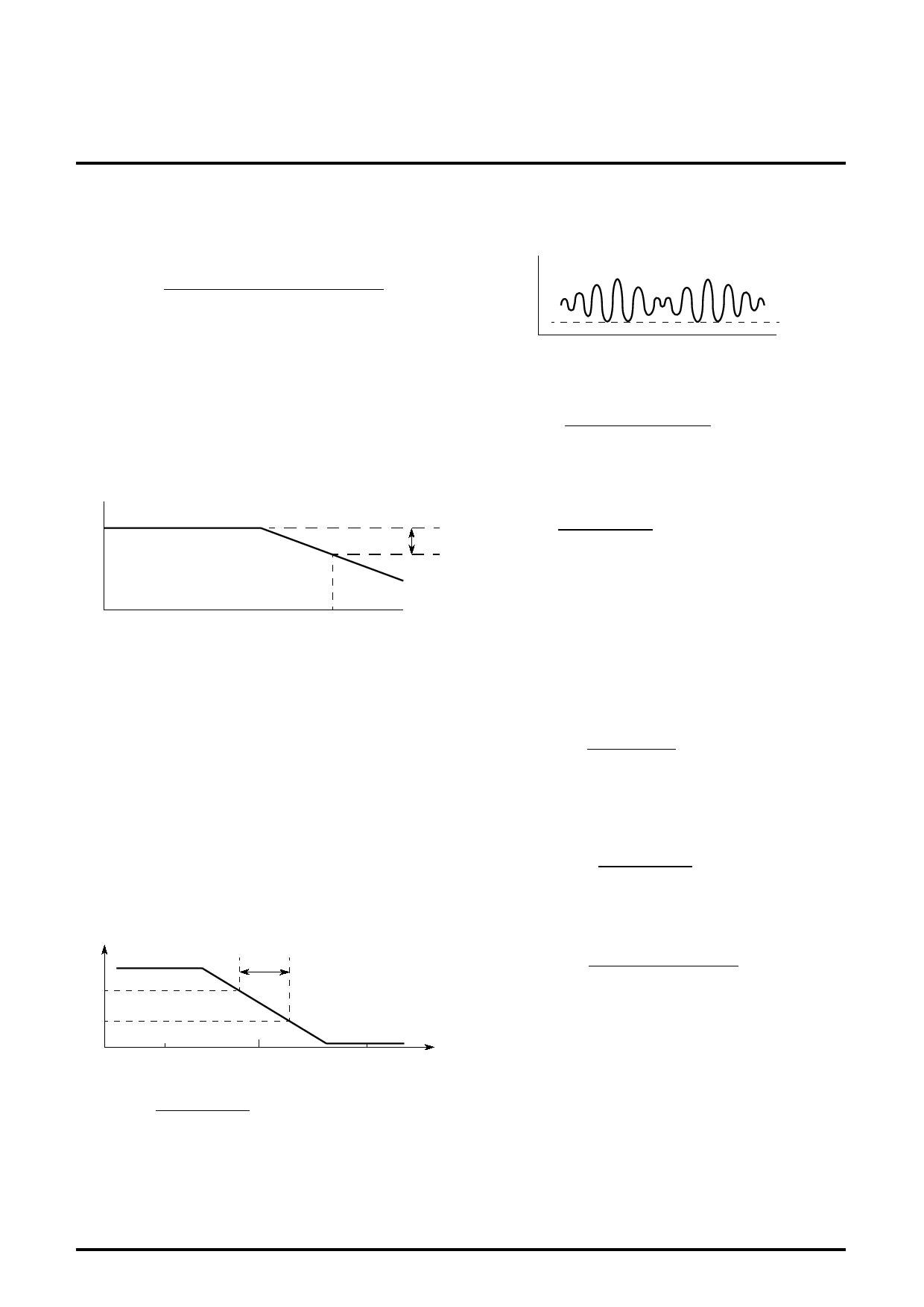
Vf Video frequency characteristics
1. Input SG4 and set the frequency f2 to 44.75MHz so that the beat
element of 1MHz is output to pin 57.
2. Then set the applied voltage at pin 60 so that the beat element of
1MHz at pin 57 may be 100dBµ.
3. Decrease f2 to the level at which the beat element becomes 3dB
smaller than the element of 1MHz, and read the value at that
level.
P57 100dBµ
3dB
IM Intermodulation
1. Adjust the applied voltage at pin 60 so that the lowest output
signal voltage at pin 57 is 2.2V.
P57
2.2V
2. Measure elements of 0.92MHz and 3.579545MHz of output at
pin 57.
3. IM is defined as follows:
IM=20log
Element of 0.92MHz
Element of 3.579545MHz
(dB)
ATT Maximum attenuation
1. Measure the element of 400Hz of output at pin 51.
2. ATT=20log
V0AFmax
Measured value
(dB)
1MHz
BW
Vin min. Input sensitivity
1. Decrease SG5 level until the video detector output is 3dB
smaller then the measured value of Parameter V3 “Video
detector output”.
Vin max. Maximum permissible input
1. Input 90dBµ SG6.
2. VA is the output level at pin 57. Increase SG6 voltage until the
output at pin 57 becomes 3dB smaller than VA. The input levell at
that time is the maximum permissible input.
µAFTN AFT detector sensitivity
V58H Maximum AFT voltage, V58L Minimum AFT voltage
See the following figure.
P1 V1HN
∆f
5.0V
3.0V
44.75Mz
f0
V1LN
46.75MHz
f
µAFTN is defined as follows:
µAFTN=
(5.0-3.0)×103mV (mV/kHz)
∆f kHz
LIM Input limiting sensitivity
Decrease the input level of SG18. Measure the input level when the
element of 400Hz at pin 52 is 3dB smaller than V0AFM (S6:
Maximum AF output (6.0M)).
AMR
1. Vam is the element of 400Hz at pin 52.
2. AMR is defined as follows:
AMR=20log
V0AF (mVrms)
Vam (mVrms)
(dB)
AF S/N
1. Measure the noise (20Hz to 100kHz) of output at pin 52.
2. AF S/N is defined as follows:
AF S/N=20log
V0AFmax
(dB)
Measured value
GEAu EXT Audio GAIN
Input SG22 at pin 53, and measure the output VP-P at pin 49.
GAIN=20log
Input signal VP-P
Output signal VP-P (pin49)
(dB)
Cn1 Output signal amplitude 1
Cn2 Output signal amplitude 2
1. Input SS from pin 36 IN.
2. Measure output amplitude, Cn1 and Cn2, at pins 18 and 20
respectively.
11
Share Link: 