SPT2210SCT 查看數據表(PDF) - Signal Processing Technologies
零件编号
产品描述 (功能)
生产厂家
SPT2210SCT Datasheet PDF : 22 Pages
| |||
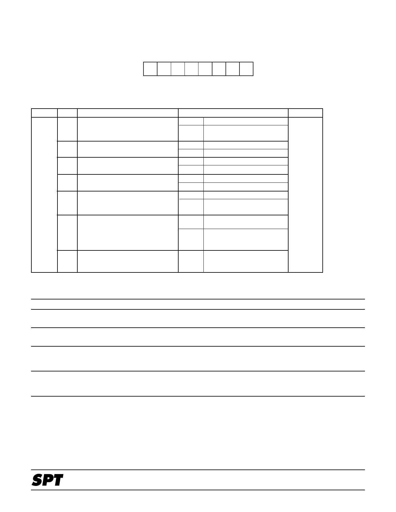
COMMAND REGISTER DESCRIPTIONS
COMMAND REGISTER CR1
CR1 (Address = 00H)
D7 D6 D5 D4 D3 D2 D1 D0
MSB
LSB
Table VI – Command Register CR1 Description Table
Address Bit #
00H
7
6
5
4
3
2
1,0
Function
Software reset
Test bar
Not used
Not used
Color kill
Cr/Cb inversion
Chroma key control. Set multiplex
mode of YD7...0 and CD7...0 video
input, and GD3...0 graphics input
Bit Setting /Description
0 Normal operation
1 Reset; all registers returned
to default
0 Normal operation
1 Color test bar is generated
0 Use fixed at 0
1
0 Use fixed at 0
1
0 Normal operation
1 Monochromatic (black and
white) image is output
0 According to the order
specified by the CBF pin
1 According to the order
specified by the inverted
CBF pin
See table VII
Default
02H
Table VII – Multiplexing Mode (Command Register 1)
D1
D0
0
0
0
1
1
0
1
1
Mode
Graphics Mode
Video Mode
Chroma Key Mode
External Key Mode
Operation
GD3…0 is displayed irrespective of the KEY terminal pin state. The
transparent color cannot be specified in this mode.
YD7…0 and CD7…0 are always selected irrespective of the state of the
KEY terminal.
YD7…0 and CD7…0 are displayed only at the parts in which transpar-
ent colors are specified by means of GD3…0. GD3…0 is displayed in all
other parts.
YD7…0 and CD7…0 are displayed when the KEY terminal pin is set to
logic 0. GD3…0 is displayed when the KEY terminal is set to logic 1.
Transparent colors cannot be specified in this mode.
SPT
SPT2210
10
8/22/00
Share Link: 