IR2214 查看數據表(PDF) - Unspecified
零件编号
产品描述 (功能)
生产厂家
IR2214 Datasheet PDF : 28 Pages
| |||
ADVANCE DATA
Data Sheet No. PD60213
IR2214SS/IR22141SS
HALF-BRIDGE GATE DRIVER IC
Features
Product Summary
• Floating channel up to +1200V
• Soft overcurrent shutdown
• Synchronization signal to synchronize shut down
with the other phases
• Integrated desaturation detection circuit
• Two stage turn on output for di/dt control
• Separate pull-up/pull-down output drive pins
• Matched delay outputs
• Under voltage lockout with hysteresis band
VOFFSET
1200V max.
IO+/- (typ.)
2.0 A / 3.0A
VOUT
10.4V - 20V
Deadtime matching (max) 75nsec
Deadtime (typ)
330nsec
Desat blanking time (typ) 3µsec
DSH,DSL input voltage
Description
threshold (typ)
8.0V
The IR2214SS/IR22141SS) is a gate driver suited to drive
Soft shutdown time (typ) 9.6µsec
a single half bridge in power switching applications. The
high gate driving capability (2A source, 3A sink) and the
low quiescent current enable bootstrap supply techniques in medium power
systems. The IR2214SS/IR22141SS driver features full short circuit protection by
Package
means of the power transistor desaturation detection. The IR2214SS/IR22141SS
manages all the half-bridge faults by turning off smoothly the desaturated tran-
sistor through the dedicated soft shut down pin, therefore preventing over-volt-
ages and reducing EM emissions. In multi-phase system IR2214SS/IR22141SS
drivers communicate using a dedicated local network (SY_FLT and FAULT/SD
signals) to properly manage phase-to-phase short circuits. The system controller
may force shutdown or read device fault state through the 3.3 V compatible CMOS
I/O pin (FAULT/SD). To improve the signal immunity from DC-bus noise, the
24-Lead SSOP
control and power ground use
dedicated pins enabling
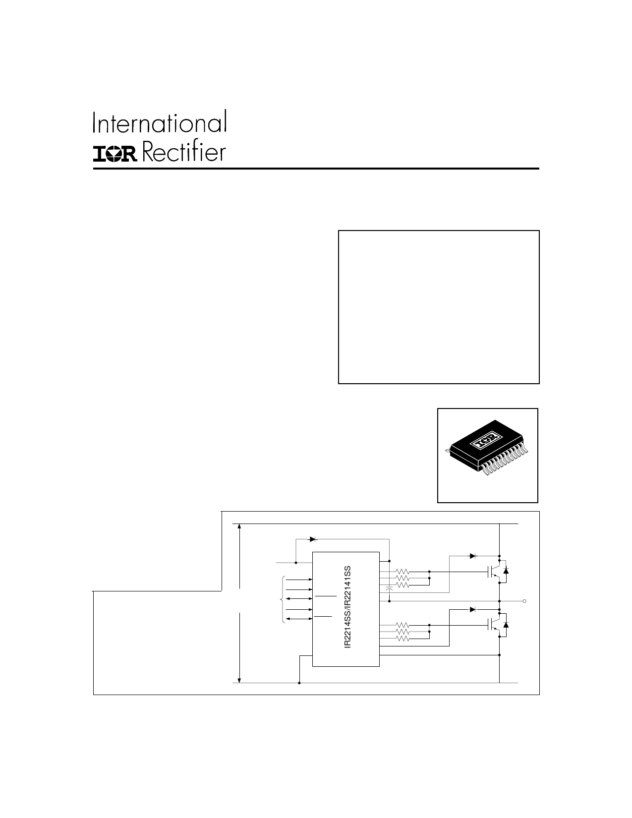
DC+
low-side emitter current
sensing as well. Under voltage
conditions in floating and low
voltage circuits are managed
15 V
VCC
VB
independently.
HOP
LIN
HON
SSDH
HIN
DC BUS uP,
Typical Connection (1200V) Control
FAULT/SD
FLT_CLR
DSH
VS
Motor
SY_FLT
LOP
(Refer to Lead Assignments for
LON
correct pin configuration). This/
SSDL
These diagram(s) show electrical
DSL
connections only. Please refer to
VSS
COM
our Application Notes and
DesignTips for proper circuit
board layout.
DC-
www.irf.com
1
Share Link: 