HFBR-53D5 查看數據表(PDF) - Avago Technologies
零件编号
产品描述 (功能)
生产厂家
HFBR-53D5 Datasheet PDF : 16 Pages
| |||
8
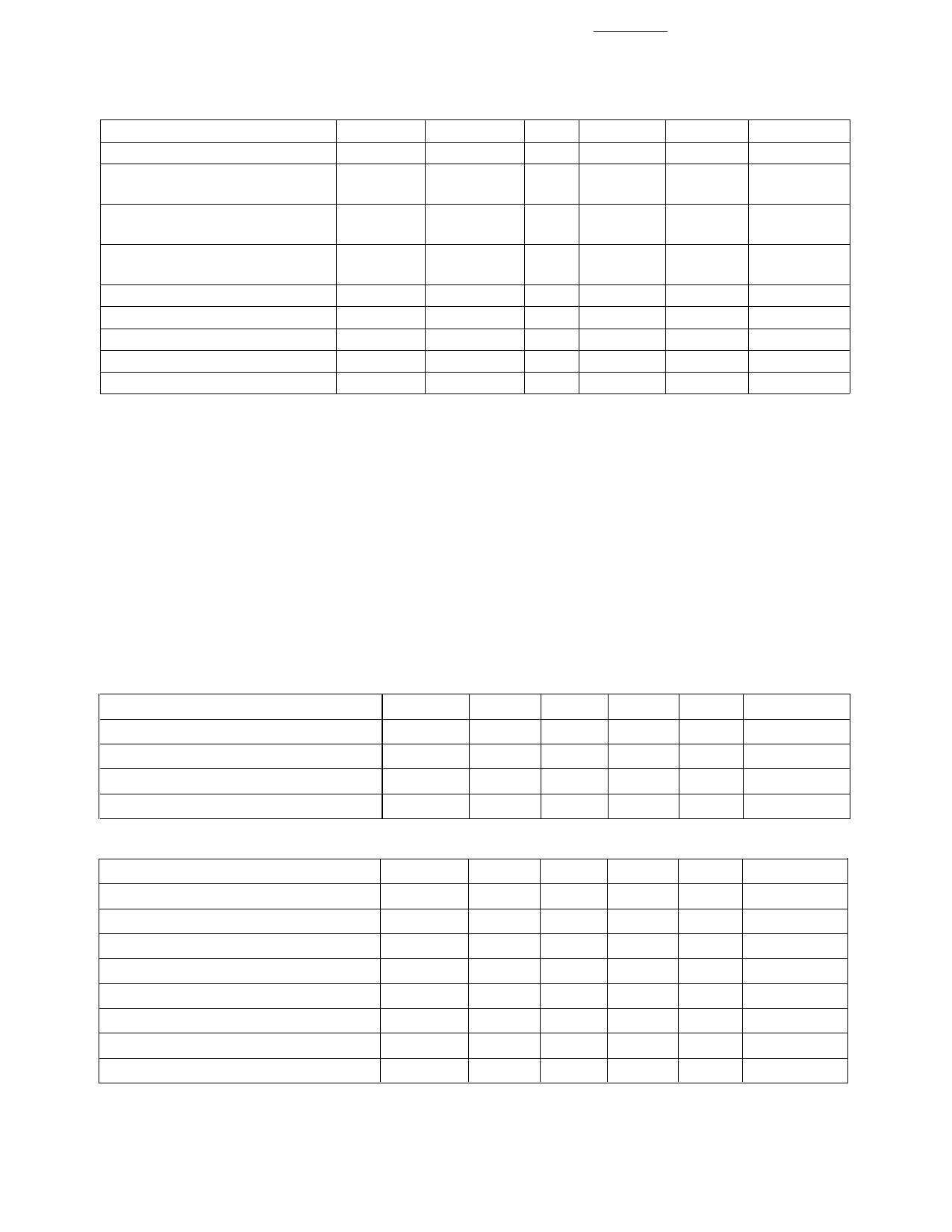
Receiver Optical Characteristics
(TA = 0°C to +70°C, VCC = 4.75 V to 5.25 V)
Parameter
Symbol
Min.
Typ. Max.
Unit Reference
Input Optical Power
PIN
–17
Stressed Receiver Sensitivity
62.5 µm
50 µm
0
dBm avg.
7
–12.5 dBm avg.
8
–13.5 dBm avg.
8
Stressed Receiver Eye
201
Opening at TP4
ps
6, 9
Receive Electrical 3 dB
Upper Cutoff Frequency
1500
MHz
10
Operating Center Wavelength
λC
770
Return Loss
12
860
nm
dB
11
Signal Detect – Asserted
PA
Signal Detect – Deasserted
PD
–30
Signal Detect – Hysteresis
PA – PD
1.5
–18 dBm avg.
dBm avg.
dB
Notes:
1. The maximum Optical Output Power complies with the IEEE 802.3z specification, and is class 1 laser eye safe.
2. Optical Extinction Ratio is defined as the ratio of the average output optical power of the transmitter in the high (“1”) state to the low (“0”) state.
The transmitter is driven with a Gigabit Ethernet 1250 MBd 8B/10B encoded serial data pattern. This Optical Extinction Ratio is expressed in
decibels (dB) by the relationship 10log(Phigh avg/Plow avg).
3. These are unfiltered 20-80% values.
4. Laser transmitter pulse response characteristics are specified by an eye diagram (Figure 1). The characteristics include rise time, fall time, pulse
overshoot, pulse undershoot, and ringing, all of which are controlled to prevent excessive degradation of the receiver sensitivity. These parameters
are specified by the referenced Gigabit Ethernet eye diagram using the required filter. The output optical waveform complies with the requirements
of the eye mask discussed in section 38.6.5 and Fig. 38-2 of IEEE 802.3z.
5. CPR is measured in accordance with EIA/TIA-526-14A as referenced in 802.3z, section 38.6.10.
6. TP refers to the compliance point specified in 802.3z, section 38.2.1.
7. The receive sensitivity is measured using a worst case extinction ratio penalty while sampling at the center of the eye.
8. The stressed receiver sensitivity is measured using the conformance test signal defined in 802.3z, section 38.6.11. The conformance test signal is
conditioned by applying deterministic jitter and intersymbol interference.
9. The stressed receiver jitter is measured using the conformance test signal defined in 802.3z, section 38.6.11 and set to an average optical power 0.5
dB greater than the specified stressed receiver sensitivity.
10. The 3 dB electrical bandwidth of the receiver is measured using the technique outlined in 802.3z, section 38.6.12.
11. Return loss is defined as the minimum attenuation (dB) of received optical power for energy reflected back into the optical fiber.
HFCT-53D5 Family, 1300 nm FP/Laser, Transmitter Electrical Characteristics
(TA = 0˚C to +70˚C, VCC = 4.75 V to 5.25 V)
Parameter
Symbol Min.
Typ. Max. Unit Reference
Supply Current
ICCT
65
130 mA
Power Dissipation
PDIST
0.35 0.68
W
Data Input Current – Low
IIL
–350
0
µA
Data Input Current – High
IIH
16
350
µA
Receiver Electrical Characteristics (TA = 0˚C to +70˚C, VCC = 4.75 V to 5.25 V)
Parameter
Symbol Min. Typ. Max. Unit
Supply Current
ICCR
120 140 mA
Power Dissipation
PDISR
0.53 0.68
W
Data Output Voltage – Low
VOL – VCC –1.950
–1.620 V
Data Output Voltage – High
VOH – VCC –1.045
–0.740 V
Data Output Rise Time
tr
0.40
ns
Data Output Fall Time
tf
0.40
ns
Signal Detect Output Voltage – Low VOL – VCC –1.950
–1.620 V
Data Output Voltage – High
VOH – VCC –1.045
–0.740 V
Reference
1
2
2
3
3
2
2
Notes:
1. Power dissipation value is the power dissipated in the receiver itself. It is calculated as the sum of the products of VCC and ICC minus the sum of the
products of the output voltages and currents.
2. These outputs are compatible with 10 K, 10 KH, and 100 K ECL and PECL inputs.
3. These are 20-80% values.
Share Link: 