MKT1820727106MG 查看數據表(PDF) - Vishay Semiconductors
零件编号
产品描述 (功能)
生产厂家
MKT1820727106MG Datasheet PDF : 17 Pages
| |||
www.vishay.com
MKT1820
Vishay Roederstein
EXAMPLE OF ORDERING CODE
TYPE
CAPACITANCE CODE
MKT1820
410
VOLTAGE CODE
06
TOLERANCE CODE (1)
5
PACKAGING CODE
G
MOUNTING
Normal Use
The capacitors are designed for mounting on printed-circuit boards. The capacitors packed in bandoleers are designed for
mounting on printed-circuit boards by means of automatic insertion machines.
For detailed tape specifications refer to packaging information www.vishay.com/docs?28139
Specific Method of Mounting to Withstand Vibration and Shock
In order to withstand vibration and shock tests, it must be ensured that the stand-off pips are in good contact with the
printed-circuit board.
• For pitches 15 mm the capacitors shall be mechanically fixed by the leads
• For larger pitches the capacitors shall be mounted in the same way and the body clamped
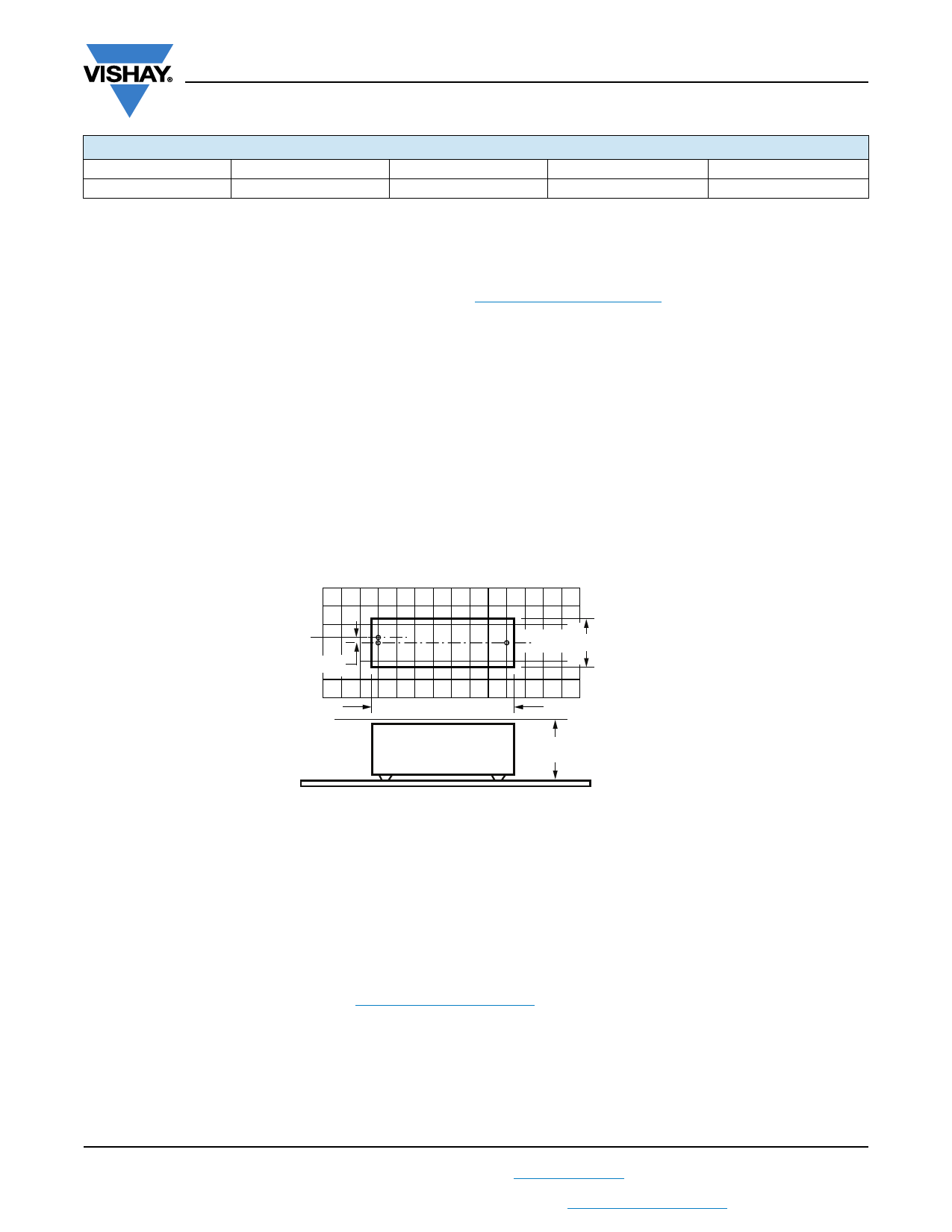
SPACE REQUIREMENTS FOR PRINTED-CIRCUIT BOARD APPLICATIONS AND DIMENSION
TOLERANCES
For the maximum product dimensions and maximum space requirements for length (Imax.), width (wmax.), and height (hmax.)
following tolerances must be taken in account in the envelopment of the components as shown in the drawings below:
• For products with pitch 15 mm, w = l = 0.3 mm, and h = 0.1 mm
• For products with 15 mm < pitch 27.5 mm, w = l = 0.5 mm, and h = 0.1 mm
• For products with pitch = 37.5 mm, w = l = 0.7 mm, and h = 0.5 mm
• For products with pitch = 52.5 mm, w = l = 1.0 mm, and h = 0.5 mm
Eccentricity defined as in drawing. The maximum eccentricity is smaller than or equal to the lead diameter of the product
concerned.
Eccentricity
wmax. = w + Δw
Imax. = I + ΔI
CBA116
hmax. = h + Δh
Seating plane
For the minimum product dimensions for length (lmin.), width (wmin.), and height (hmin.) following tolerances of the components
are valid:
lmin. = l - l, wmin. = w - w, and hmin. = h - h following
• For products with pitch 10 mm, l = 0.3 mm, and w = h = 0.3 mm
• For products with pitch = 15 mm, l = 0.5 mm, and w = h = 0.5 mm
• For products with 15 mm < pitch 27.5 mm, l = 1.0 mm. and w = h = 0.5 mm
• For products with pitch = 37.5 mm, l = 1.0 mm, and w = h = 1.0 mm
• For products with pitch = 52.5 mm, l = 1.5 mm, and w = h = 1.0 mm
SOLDERING CONDITIONS
For general soldering conditions and wave soldering profile, we refer to the application note:
“Soldering Guidelines for Film Capacitors”: www.vishay.com/doc?28171
Storage Temperature
Tstg = -25 °C to +35 °C with RH maximum 75 % without condensation
Ratings and Characteristics Reference Conditions
Unless otherwise specified, all electrical values apply to an ambient free temperature of 23 °C ± 1 °C, an atmospheric pressure
of 86 kPa to 106 kPa and a relative humidity of 50 % ± 2 %.
For reference testing, a conditioning period shall be applied over 96 h ± 4 h by heating the products in a circulating air oven at
the rated temperature and a relative humidity not exceeding 20 %.
Revision: 02-Feb-18
8
Document Number: 26011
For technical questions, contact: dc-film@vishay.com
THIS DOCUMENT IS SUBJECT TO CHANGE WITHOUT NOTICE. THE PRODUCTS DESCRIBED HEREIN AND THIS DOCUMENT
ARE SUBJECT TO SPECIFIC DISCLAIMERS, SET FORTH AT www.vishay.com/doc?91000
Share Link: 