11995-202 查看數據表(PDF) - AMI Semiconductor
零件编号
产品描述 (功能)
生产厂家
11995-202 Datasheet PDF : 14 Pages
| |||
AMERICAN MICROSYSTEMS, INC.
FS6233-01
Motherboard Clock Generator IC
September 2000
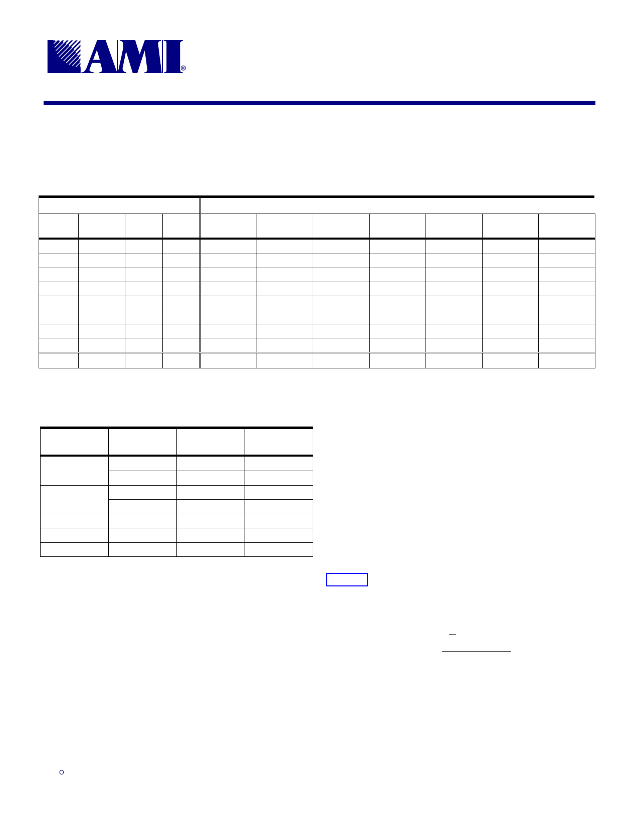
2.0 Programming Information
Table 4: Function/Clock Enable Configuration
CONTROL INPUTS (1)
PWR_
DWN#
SEL
133/100#
SEL_A
SEL_B
HOST_P
1:2
HOST_N
1:2
CLOCK OUTPUTS (MHz)
MREF_P,
MREF_N
CK66_
0:2
PCI_
0:9
1
0
0
0
100.00
100.00
50.00
66.67
33.33
1
0
0
1
reserved
reserved
reserved
reserved
reserved
1
0
1
0
reserved
reserved
reserved
reserved
reserved
1
0
1
1
tristate
tristate
tristate
tristate
tristate
1
1
0
0
133.33
133.33
66.67
66.67
33.33
1
1
0
1
reserved
reserved
reserved
reserved
reserved
1
1
1
0
reserved
reserved
reserved
reserved
reserved
1
1
1
1
XIN ÷ 2
XIN ÷ 2
XIN ÷ 4
XIN ÷ 4
XIN ÷ 8
0
X
X
X
2 × IREF
tristate
low
low
low
1. It is expected that the Control Inputs will be defined on power-up and will not change during normal operation.
CK48_
0:1
48.008
reserved
reserved
tristate
48.008
reserved
reserved
XIN ÷ 2
low
REF
14.318
reserved
reserved
tristate
14.318
reserved
reserved
XIN
low
Table 5: Synthesis Error
CLOCK
TARGET
(MHz)
ACTUAL
(MHz)
DEVIATION
(ppm)
HOST_P1:2,
HOST_N1:2
100.0000
133.3333
99.9963
133.3072
-36.657
-195.924
MREF_P,
MREF_N
50.0000
66.6667
49.9982
66.6536
-36.657
-195.924
CK66
66.6667
66.6642
-36.657
PCI
33.3333
33.3321
-36.657
CK48 (1)
48.000
48.008
+167
1. 48MHz USB clock is required to be +167ppm off from 48.000MHz to conform to USB
standards.
2. Spread spectrum is disabled
3.0 HOST Buffer Current Control
The current supplied at the HOST outputs is controlled by
two parameters:
1) the value of the programming resistor from the IREF
pin to ground (VSS), and
2) the multiplier factor determined by the logic setting of
the ISEL_0 and ISEL_1 pins.
3.1 Current Reference
The HOST output current is a mirrored and scaled copy
of the reference current flowing through the programming
resistor on the IREF pin. Conceptually, the circuit given in
Figure 2 shows how the mirror current is generated.
The voltage that appears at the IREF pin is one-third of
the voltage at the VDD_I pin. The reference current is
1 × VDD_I
I REF = 3 RIREF
.
ISO9001
3.2 Current Scaling
The mirrored reference current can be increased by
adding one or more copies of the mirror current together.
The additional current is controlled by the logic settings
on the ISEL_0 and ISEL_1 pins.
9.18.00
3
Share Link: 