A3195EU 查看數據表(PDF) - Allegro MicroSystems
零件编号
产品描述 (功能)
生产厂家
A3195EU Datasheet PDF : 10 Pages
| |||
3195
PROTECTED, HIGH-TEMP.,
ACTIVE PULL-DOWN
HALL-EFFECT LATCH
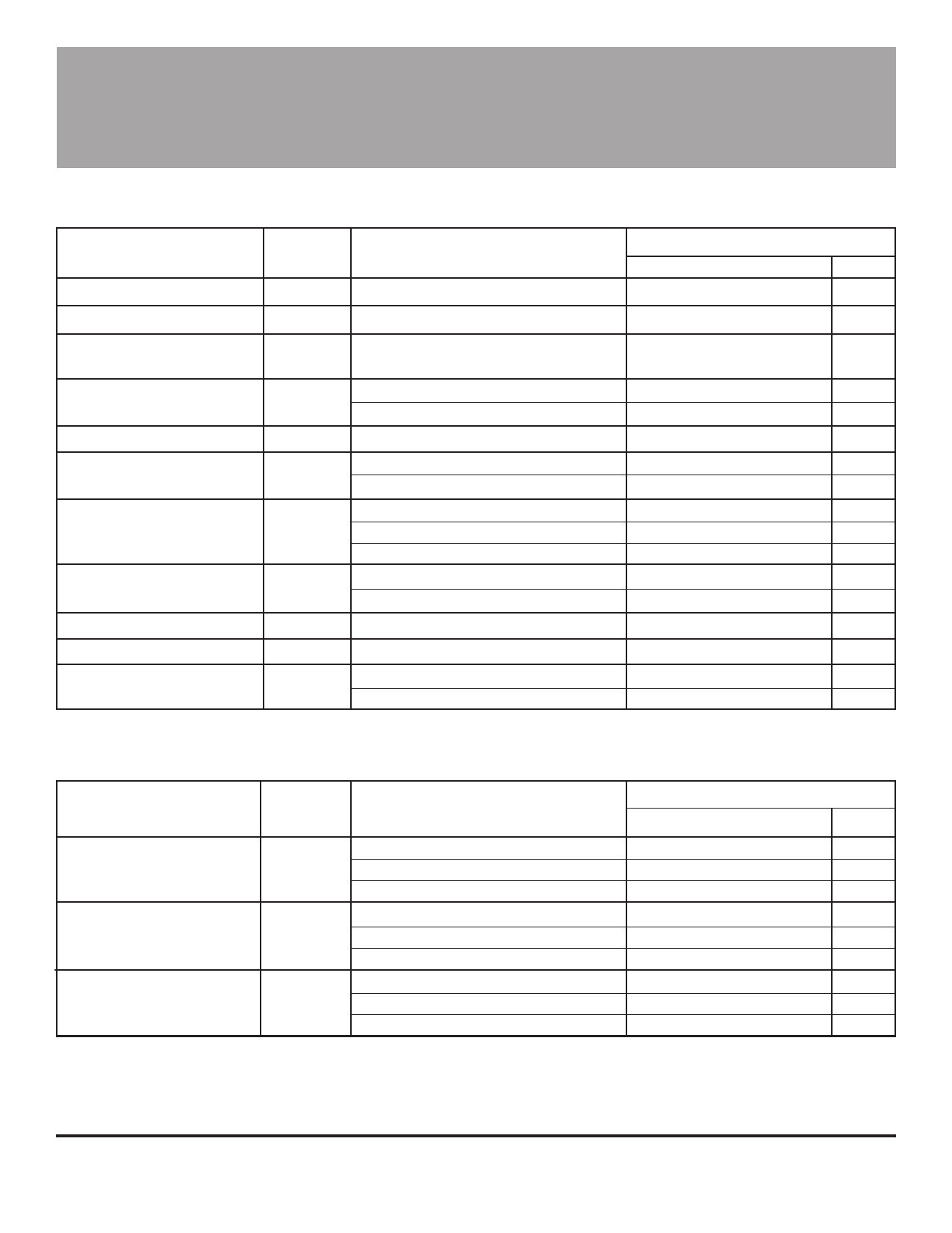
ELECTRICAL CHARACTERISTICS
over operating voltage and temperature range (unless otherwise specified).
Limits
Characteristic
Symbol
Test Conditions
Min.
Typ.
Max. Units
Supply Voltage
Overvoltage Shutdown*
Output Voltage, High
(Source Voltage)
VCC
VCC(OV)
VOUT(H)
Operating (but VCC x ICC VS TA limited)
3.8
12
26
V
B > BOP
28
—
55
V
B < BRP, IOUT = -20 mA
VCC -2
—
VCC -0.3 V
Output Voltage, Low
(Sink Voltage)
Output Clamp Voltage
Output Current Limit
Supply Current
Reverse Battery Current*
Output Rise Time
Output Fall Time
Package Thermal Resist.
VOUT(L)
VOUT(CLMP)
IOUTMAX
ICC
IRCC
tr
tf
RθJA
B > BOP, IOUT <100 µA
B > BOP, IOUT = 5 mA
B < BRP, VCC > 26 V, IOUT = 0
B < BRP, VCC = 12 V
B > BOP, VOUT < 14 V
B < BRP, VCC = 18 V, IOUT = 0
B > BOP, VCC = 18 V, IOUT = 0
VCC= +115 V*
VRCC = -35 V*
VRCC = -100 V*
CL = 20 pF, RL = 330 Ω
CL = 20 pF, RL = 330 Ω
“LT” Package
“U” Package
—
0.1
0.2
V
—
0.25
0.5
V
15
18
21
V
-26
—
8.0
—
-70 mA
25
mA
—
6.0
9.0 mA
—
8.0
12
mA
—
8.0
17
mA
—
-0.1
-5.0 mA
—
-0.1
-10 mA
—
0.12
2.0
µs
—
0.30
5.0
µs
—
258
—
183
— °C/W
— °C/W
MAGNETIC CHARACTERISTICS
over operating voltage range (unless otherwise specified).
Characteristic
Symbol
Test Conditions
Min.
Operate Point
Release Point
Hysteresis
(BOP - BRP)
BOP
TA = -40°C
TA = +25°C
TA = Maximum
BRP
TA = -40°C
TA = +25°C
TA = Maximum
Bhys
TA = -40°C
TA = +25°C
TA = Maximum
60
50
40
-200
-160
-150
150
130
110
NOTES: Negative current is defined as coming out of (sourcing) the output.
BOP = magnetic operate point (output turns ON); BRP = magnetic release point (output turns OFF).
As used here, negative flux densities are defined as less than zero (algebraic convention).
Typical values are at TA = +25°C and VCC = 12 V.
* Fault condition. Device is shut down and operation is not possible.
Limits
Typ.
Max.
125
200
110
160
100
150
-125
-60
-110
-50
-100
-40
250
—
220
—
200
—
Units
G
G
G
G
G
G
G
G
G
Share Link: 