DMS-30LCD жҹҘзңӢж•ёж“ҡиЎЁпјҲPDFпјү - Murata Power Solutions
йӣ¶д»¶зј–еҸ·
дә§е“ҒжҸҸиҝ° (еҠҹиғҪ)
з”ҹдә§еҺӮ家
DMS-30LCD Datasheet PDF : 6 Pages
| |||
APPLICATIONS
RShunt = R1 = VFsr / IFsr
Where: VFsr = Full scale reading (in Volts)
IFsr = Relative full scale current (in Amps)
Example: For a meter with a 2V full scale input (1.999 full
scale reading) and a desired full scale display reading of
1000 (with an input of 20mA), VFsr = 1.000 Volts
RShunt = 1.000V/(0.020 вҖ“ 0.004)A
RShunt = 1.000V/0.016A = 62.5 Ohms
To calibrate the circuit of Figure 7, perform the following:
1. With 4mA applied, adjust the 50kО© potentiometer (R2) to
display a reading of "000" (assuming that is the desired
reading).
2. With 20mA applied, adjust the gain-adjust potentiometer on
the back of the meter to display a reading of "1999". For different full
scale readings, alter the RShunt value accordingly.
4-20mA R1
вҖ“
(+) IN HI
DMS-30LCD-1-5
8
REF OUT
ANA COMM
(вҖ“) IN LO
1
R2
+5V SUP
50k
3
5V RET
7
REF IN
120 VAC
AC to DC Converter
Figure 7. 4-to-20mA Current Loop Operation
(5V-Powered Models)
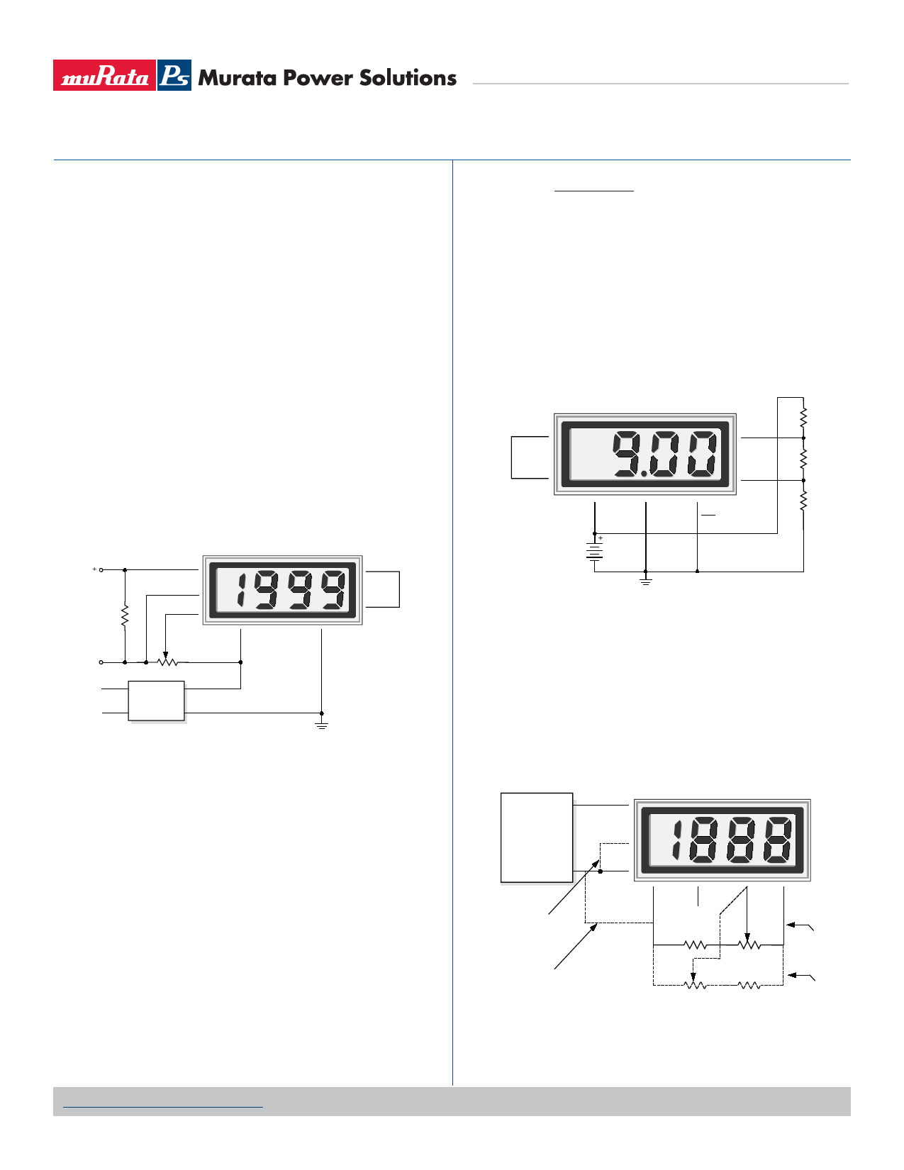
6. Power Supply Monitoring: A popular application for Murata Power
SolutionsвҖҷ low-power LCD meters is monitoring the supply voltage in
battery-operated portable equipment. Figure 8 demonstrates how a
9V-powered DMS-30LCD can be used to monitor its own supply. The
meter used is the DMS-30LCD-1-9. A three-resistor voltage divider is
used to attenuate the battery voltage and also to satisfy the require-
ment that the input voltages applied to pins 12 and 11 be at least 1.5
Volts above and below the battery voltage applied to pins 1 (+BAT-
TERY) and 3 (вҖ“BATTERY). The divider should be designed so that
1/10th the battery voltage falls across the inputs to the meter:
www.murata-ps.com/support
DMS-30LCD Series
3ВҪ Digit, LCD Display Digital Panel Voltmeters
R2
= 0.1
(R1 + R2 + R3)
Therefore, the 9V battery voltage appears to the meter inputs as 0.9V.
With the decimal point moved to its DP2 position
(pin 5 tied to pin 3), the meter reads 9.00 Volts.
The circuit can be calibrated by п¬Ғrst measuring the actual battery volt-
age with another meter and then adjusting the gain-adjust potentiom-
eter on the back of the DMS-30LCD until a similar reading is obtained.
If possible, the resistors in the divider should be Вұ1% metal-п¬Ғlm types
with TCRвҖҷs less than 50ppm/В°C.
8
REF OUT
DMS-30LCD-1-9
11
(+) IN HI
7
REF IN
1
+BAT
9V
BATTERY
вҖ“
12
(вҖ“) IN LO
3
5
вҖ“BAT
DP2
R1
45.3k
R2
10.1k
R3
45.3k
Figure 8. Power Supply Monitor
(9V-Powered Models)
7. External Gain Adjustment: Connect REFERENCE OUT
(pin 8) to REFERENCE IN (pin 7) for normal, factory calibrated, opera-
tion. Use the +1.23V REFERENCE OUT (pin 9) for applications need-
ing external gain adjustment. Figure 9 shows the wiring conп¬Ғguration
for each model. Calibration is performed with a precise, near-full-scale,
input voltage.
11
(+) IN HI
OUT
DMS-30LCD
VOLTAGE
12 CALIBRATOR
3
5V RET
COM
For 5V models tie
(вҖ“) IN LO to pin 3
12
(вҖ“) IN LO
10
ANA COMM
8
NC
8.45k, 1%
7
REF IN
For 9V models tie
(вҖ“) IN LO to pin 10
1k
10 to 20 Turns
1k
8.45k, 1%
10 to 20 Turns
Figure 9. External Gain Adjustment
9
1.23V REF
Connections
for Вұ2V and
Вұ20V models
Connections
for Вұ200mV
models
MPM_DMS30LCD.E01 Page 5 of 6
Share Link: 