HPP800A001 查看數據表(PDF) - Humirel
零件编号
产品描述 (功能)
生产厂家
HPP800A001 Datasheet PDF : 4 Pages
| |||
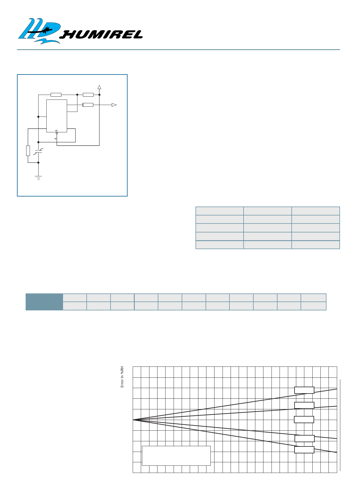
FREQUENCY OUTPUT CIRCUITS
3 TECHNICAL DATA
R2 576K
IC1
2 TR
Q3
DC 7
TLC555
5 CV
TH 6
3.5 TO 12V
R4 49.9K
R3 1K
FOUT
COMMENTS
This circuit is the typical astable design for 555. The HS1100/HS1101, used as varia-
ble capacitor, is connected to the TRIG and THRES pin. Pin 7 is used as a short circuit
pin for resistor R4.
The HS1100/HS1101 equivalent capacitor is charged through R2 and R4 to the
threshold voltage (approximately 0.67Vcc) and discharged through R2 only to the trig-
ger level (approximately 0.33Vcc) since R4 is shorten to ground by pin 7.
Since the charge and discharge of the sensor run through different resistors, R2 and
R4, the duty cycle is determined by :
R1
909K
HS11XX
180p@55%RH
thigh = C@%RH*(R2+R4)*ln2
tlow = C@%RH*R2*ln2
F = 1/(thigh+tlow) = 1/(C@%RH*(R4+2*R2)*ln2)
Output duty cycle = thigh*F = R2/(R4+2*R2)
GND
BILL OF MATERIAL AVAILABLE ON REQUEST
To provide an output duty cycle close to 50%, R4 should be very low compared to R2
but never under a minimum value.
Resistor R3 is a short circuit protection. 555 must be a CMOS version.
REMARK
R1 unbalances the internal temperature compensation scheme of the
555 in order to introduce a temperature coefficient that matches the
HS1100/HS1101 temperature coefficient. In all cases, R1 should be a 1%
resistor with a maximum of 100ppm coefficient temperature like all
other R-C timer resistors. Since 555 internal temperature compensation
changes from one trademark to one other, R1 value should be adapted
to the specific chip. To keep the nominal frequency of 6660Hz at 55%RH,
R2 also needs slight adjustment as shown in the table.
555 Type
TLC555 (Texas)
TS555 (STM)
7555 (Harris)
LMC555 (National)
R1
R2
909kΩ
576kΩ
100nF capacitor
523kΩ
1732kΩ
549kΩ
1238kΩ
562kΩ
For a frequency of 6660Hz at 55%RH
Typical Characteristics for Frequency Output Circuits
REFERENCE POINT AT 6660Hz FOR 55%RH / 25°C
RH
0
10
20
30
40
50
60
70
80
90
100
Frequency
7351
7224
7100
6976
6853
6728
6600
6468
6330
6186
6033
Typical for a 555 Cmos type. TLC555 (RH : Relative Humidity in %, F : Frequency in Hz)
Polynomial response :
Fmes(Hz) = F55(Hz)(1.1038-1.936810-3*RH+3.011410-6*RH2-3.440310-8*RH3)
Measurement Error
vs
Stray Capacitance
A special attention is required
in order to minimize stray
capacitance in the layout.
The added capacitance will
act as a parallel capacitance
with the sensor and create a
measurement error.
10
8
6
12% RH
4
33% RH
2
0
55% RH
-2
-4
-6
Nominal Capacitance : 180pF
Nominal Humidity : 55%RH
-8
Frequency Range : 0kHz to 25kHz
75.5% RH
97.5% RH
-10
0 1 2 3 4 5 6 7 8 9 10 11 12 13 14 15 16 17 18 19 20 21 22 23 24 25
Stray capacitance (pF)
HPC001 Rev. 7 June 2002
Share Link: 